
Electric caulking gun

Active Publication Date: 2009-02-12
TECHWAY INDAL
View PDF8 Cites 71 Cited by
  • Summary
  • Abstract
  • Description
  • Claims
  • Application Information

AI Technical Summary

Benefits of technology

[0007]The main objective of the present invention is to provide an electric caulking gun that can be used conveniently.

Problems solved by technology

However, when the conventional caulking gun is used with the caulking tube, the drive ring can only move in a single direction to make the pushing bracket moving forward and this may make the gel flow out of the caulking tube if the person does not use the conventional caulking gun.
This may make the working place dirty and waste the gel of the caulking tube and inconvenient in use.

Method used


Image

  • Electric caulking gun
  • Electric caulking gun
  • Electric caulking gun

Examples


Embodiment Construction

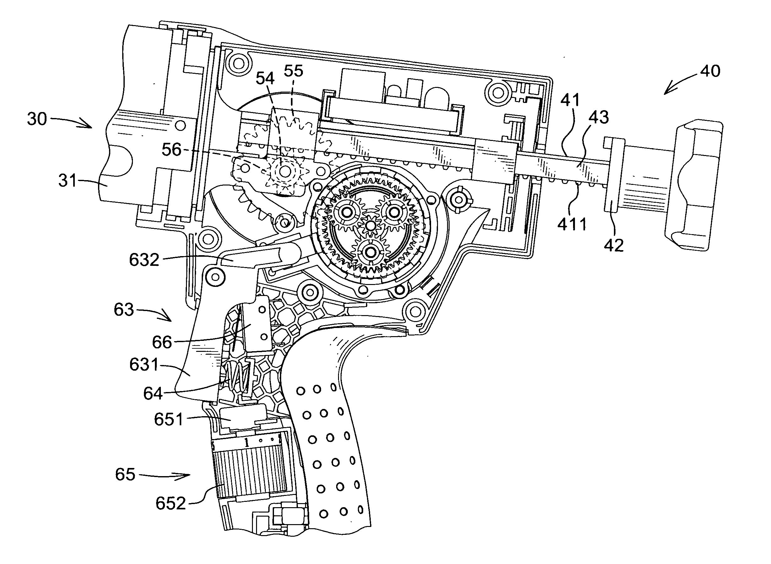
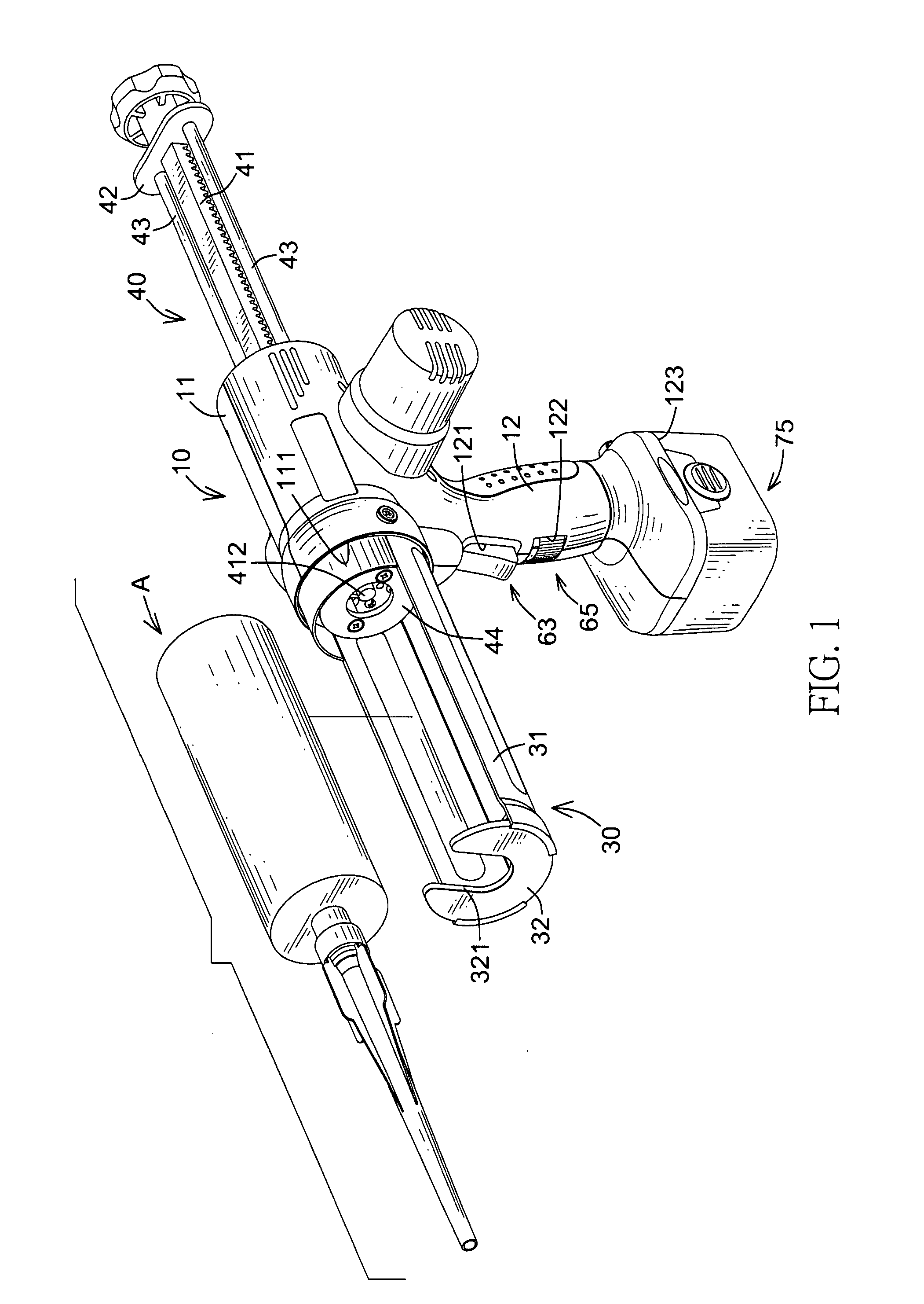
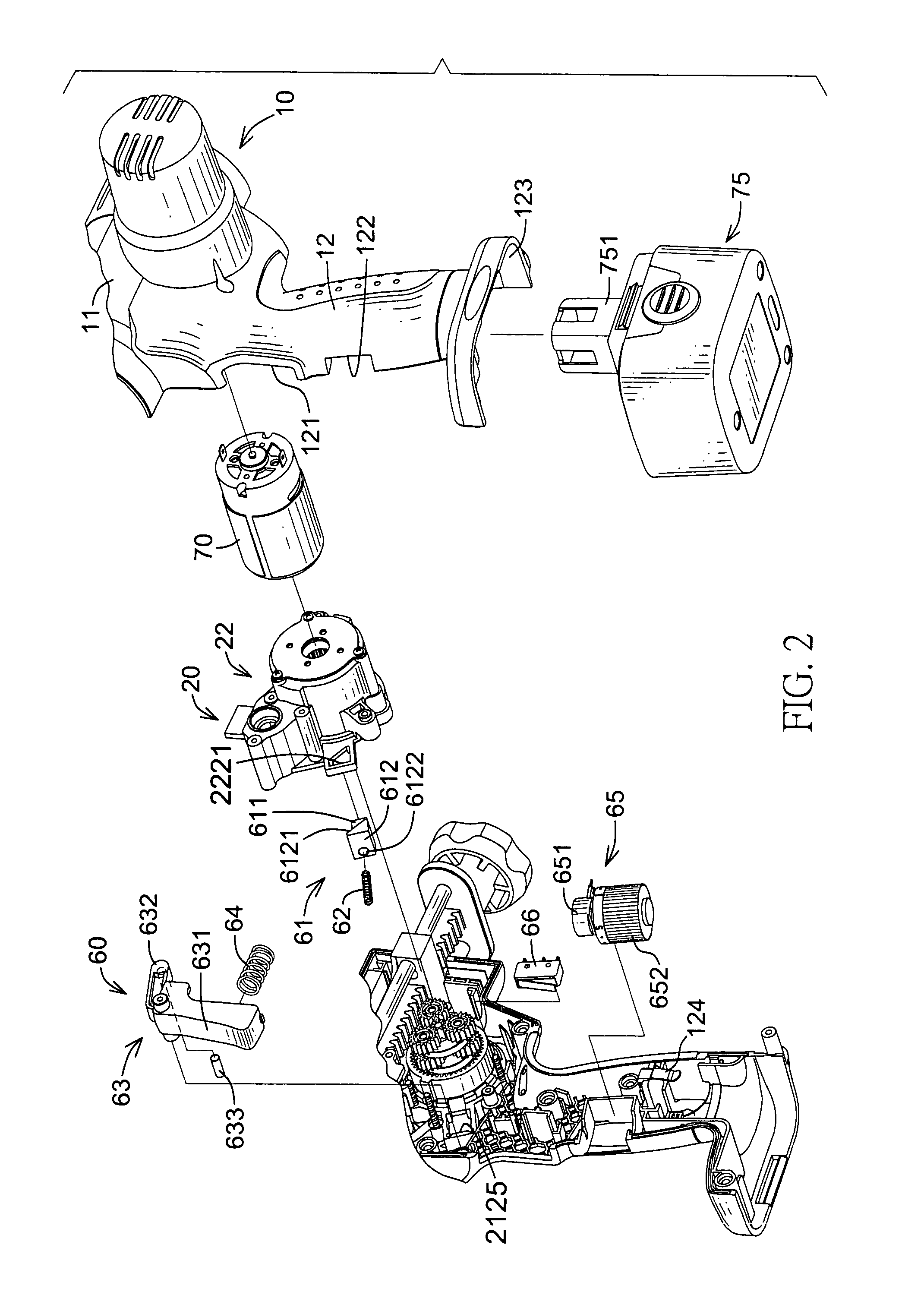
[0021]With reference to FIGS. 1 to 3, an electric caulking gun in accordance with the present invention comprises a body (10), a gearbox (20), a caulking barrel (30), a pushing device (40), a driving assembly (50), an actuating assembly (60), a motor (70) and a power source (75).

[0022]With reference to FIGS. 1 to 4, The body (10) is hollow, is implemented with two half-casings and has a mounting section (1) and a handle section (12).

[0023]The mounting section (11) has a front end, a rear end, an interior, a front opening (111) and a rear opening (112). The openings (111, 112) are respectively formed in the front end and the rear end of the mounting section (11) and communicate with the interior.

[0024]The handle section (12) extends transversely from the mounting section (11) and has a top end, an lower end, a chamber, an outer surface, a connecting hole (121), an optional mounting hole (122), an optional inserting hole (123) and an optional circuit contact (124). The top end of the ...


PUM


Abstract

An electric caulking gun has a body, a gearbox, a caulking barrel, a pushing device, a driving assembly, an actuating assembly, a motor and a power source. The body has a mounting section and a handle section. The gearbox is mounted in the body and has a seat and a mounting sheath. The caulking barrel is connected to the gearbox. The pushing device is connected movably to the gearbox and has a rack, a linking sheet, two pushing shafts and a pushing disc. The driving assembly is mounted in the gearbox. The actuating assembly is mounted between the gearbox and the body. The motor is mounted in the body between the mounting section and the mounting sheath of the gearbox. The power source is connected detachable to the handle section of the body.

Description

BACKGROUND OF THE INVENTION[0001]1. Field of the Invention[0002]The present invention relates to a caulking gun, and more particularly relates to an electric caulking gun that can be used conveniently.[0003]2. Description of Related Art[0004]Conventional caulking gun includes a manual and an automatic type, and usually comprises a caulking barrel, a handle, a pushing bracket and a signal direction drive ring. The caulking barrel is used to hold with a caulking tube. The handle is formed with the caulking barrel and has a pressing arm. The pushing bracket is connected movably to the caulking barrel over the handle. The signal direction drive ring is mounted around the pushing bracket to push the pushing bracket moving relative to the caulking tube by the pressing arm of the handle.[0005]However, when the conventional caulking gun is used with the caulking tube, the drive ring can only move in a single direction to make the pushing bracket moving forward and this may make the gel flow...

Claims


Application Information

Patent Timeline
IPC IPC(8): B65D88/54B67D5/52G01F11/00B67D7/70
CPCB05C17/0103B05C17/00553
Inventor HSU, CHIH-HUACHENG, CHEN-CHENLIN, RUI-HENG
Owner TECHWAY INDAL
Features
  • Generate Ideas
  • Intellectual Property
  • Life Sciences
  • Materials
  • Tech Scout
  • Unparalleled Data Quality
  • Higher Quality Content
  • 60% Fewer Hallucinations
Learn More