
System and Method of Traffic Inspection and Stateful Connection Forwarding Among Geographically Dispersed Network Appliances Organized as Clusters

a network appliance and cluster technology, applied in the field of system and method of tcp connection forwarding, can solve the problems of asymmetric routing, traffic originated by a particular client may not reach a proxy device,

Active Publication Date: 2009-02-12
CA TECH INC
View PDF16 Cites 77 Cited by
  • Summary
  • Abstract
  • Description
  • Claims
  • Application Information

AI Technical Summary

Benefits of technology

The present invention provides a method for establishing a peering relationship among network appliances through an exchange of control messages. This peering relationship defines a cluster of peered network appliances, and traffic flow state information for all the network appliances of the cluster is maintained. The traffic flow state information is synchronized among the network appliances through an exchange of cluster management messages. The invention allows for the forwarding of network traffic associated with one or more traffic flows based on the state information for those flows. The traffic flow state information is maintained through an exchange of cluster management messages, and the members of the cluster are peered with each other through an exchange of cluster management messages. The invention also allows for the synchronization of traffic flow state information among peered members of a network traffic device cluster, and the traffic flow state information may be encrypted prior to synchronization.

Problems solved by technology

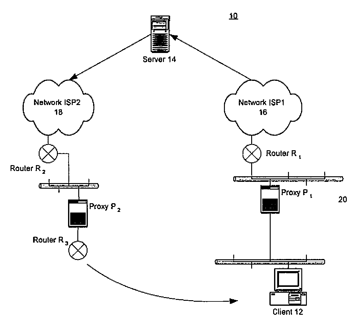
A common problem facing organizations with large enterprise networks is the problem of asymmetric routing.
This poses a problem when the proxies employ client IP spoofing.
Consequently the return traffic may not reach the proxy that intercepted the original request.
In such a case, traffic originated by a particular client may not reach a proxy device that was intercepting traffic from a server.
This would, again, trigger incorrect connection resets.

Method used


Image

  • System and Method of Traffic Inspection and Stateful Connection Forwarding Among Geographically Dispersed Network Appliances Organized as Clusters
  • System and Method of Traffic Inspection and Stateful Connection Forwarding Among Geographically Dispersed Network Appliances Organized as Clusters
  • System and Method of Traffic Inspection and Stateful Connection Forwarding Among Geographically Dispersed Network Appliances Organized as Clusters

Examples


Embodiment Construction

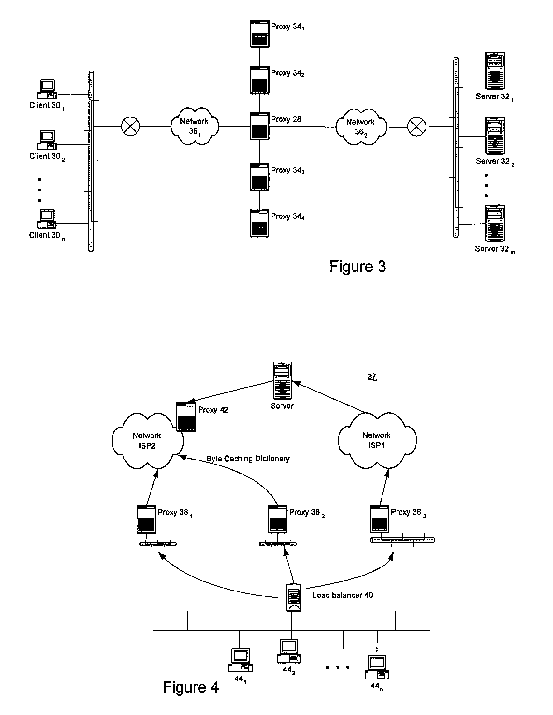
[0028]Described herein are systems and methods for TCP (and some UDP) connection forwarding in asymmetrically routed and other environments. Unlike other TCP connection forwarding schemes, the present invention allows network appliances on different network segments to peer with one another and form clusters within which TCP connections can be forwarded among cluster members for processing. In some embodiments of the invention, the TCP forwarding occurs at Layer-2 (L2), thus avoiding extended processing delays at higher layers at the forwarding appliance. Moreover, the present invention does not rely on the use of packet multicasting and multicast forwarding technology, which is not supported by all legacy routers deployed in the field.

[0029]TCP connection forwarding practiced in accordance with the present invention allows a group of clustered network appliances (proxies) to be treated as a single, virtual appliance for purposes of network policy enforcement at the connection level...


PUM


Abstract

A peering relationship among two or more network appliances is established through an exchange of control messages among the network appliances. The peering relationship defines a cluster of peered network appliances, and at each network appliance of the cluster traffic flow state information for all the network appliances of the cluster is maintained. Network traffic associated with traffic flows of the network appliances of the cluster is managed according to the state information for the traffic flows. This managing of the network traffic may include forwarding among the network appliances of the cluster (i.e., to those of the appliances handling the respective flows) at least some of the network traffic associated with one or more of the traffic flows according to the state information for the one or more traffic flows. The traffic flows may be TCP connections or UDP flows.

Description

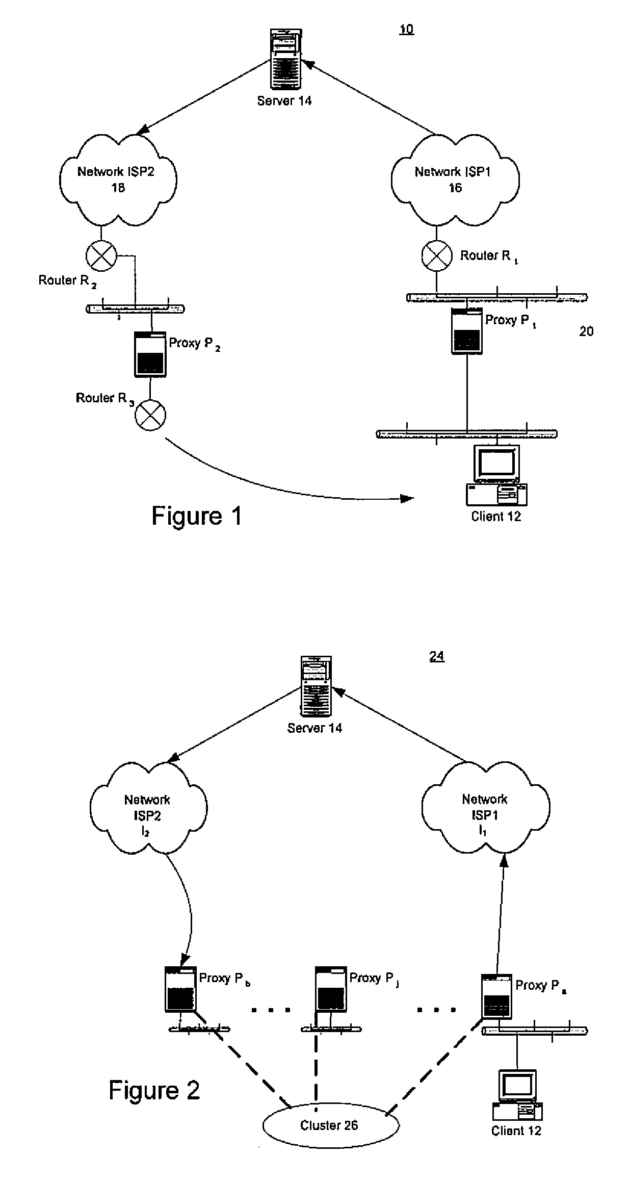
FIELD OF THE INVENTION[0001]The present invention relates to systems and methods for TCP connection forwarding in asymmetrically routed and other environments.BACKGROUND[0002]A common problem facing organizations with large enterprise networks is the problem of asymmetric routing. Such a situation can occur in a variety of contexts, but often occurs where an enterprise obtains Internet connectivity from multiple Internet Service Providers (ISPs); in other words, when the enterprise has multiple address prefixes.[0003]Refer, for example, to FIG. 1. This illustration depicts a multi-ISP environment 10 in which an enterprise network includes two proxy devices P1 and P2, which provide connectivity for a client 12 to a server 14 via two ISPs 16 and 18, respectively. Of course, this illustration depicts a rather straightforward routing path (from P1 through router R1, and from R3 through P2 and R2) for each ISP connection, whereas in other deployment scenarios the routing paths may be mor...

Claims


Application Information

Patent Timeline
Patent Type & Authority Applications(United States)
IPC IPC(8): G08C15/00
CPCH04L29/12367H04L41/0893H04L41/5003H04L43/12H04L69/162H04L67/1008H04L67/1002H04L67/1014H04L67/1023H04L61/2514H04L67/1001
Inventor LI, QINGMORDANI, PREETYHUANG, YUSHENGCHEN, HOWARD
Owner CA TECH INC
Learn More