Receiver with the function of adjusting clock signal and an adjusting method therefor
- Summary
- Abstract
- Description
- Claims
- Application Information
AI Technical Summary
Benefits of technology
Problems solved by technology
Method used
Image
Examples
Embodiment Construction
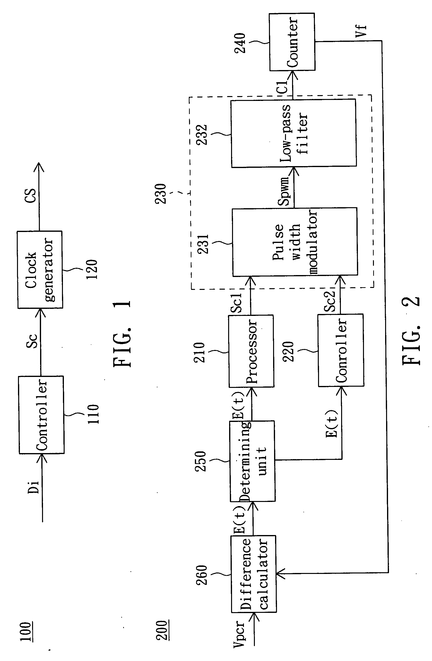
[0014]FIG. 1 shows a block diagram of the receiver according to an embodiment of the invention. Referring to FIG. 1, the receiver 100 in FIG. 1 includes a controller 110 and a clock generator 120. The controller 110 outputs a control signal Sc to control the clock generator 120 to adjust the frequency of a clock signal CS in the receiver 100. The control signal Sc is determined by the difference Di between the frequencies of the clock signal CS generated by the receiver 100 and a clock signal of a transmitter.
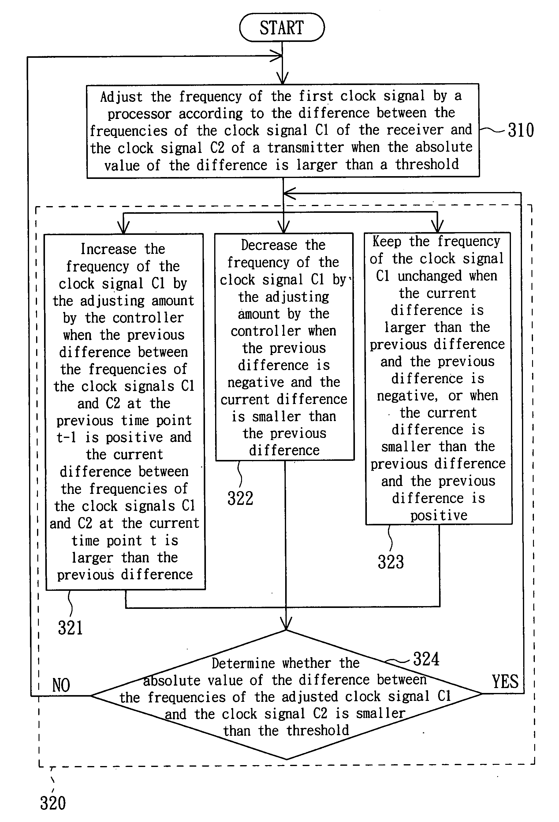
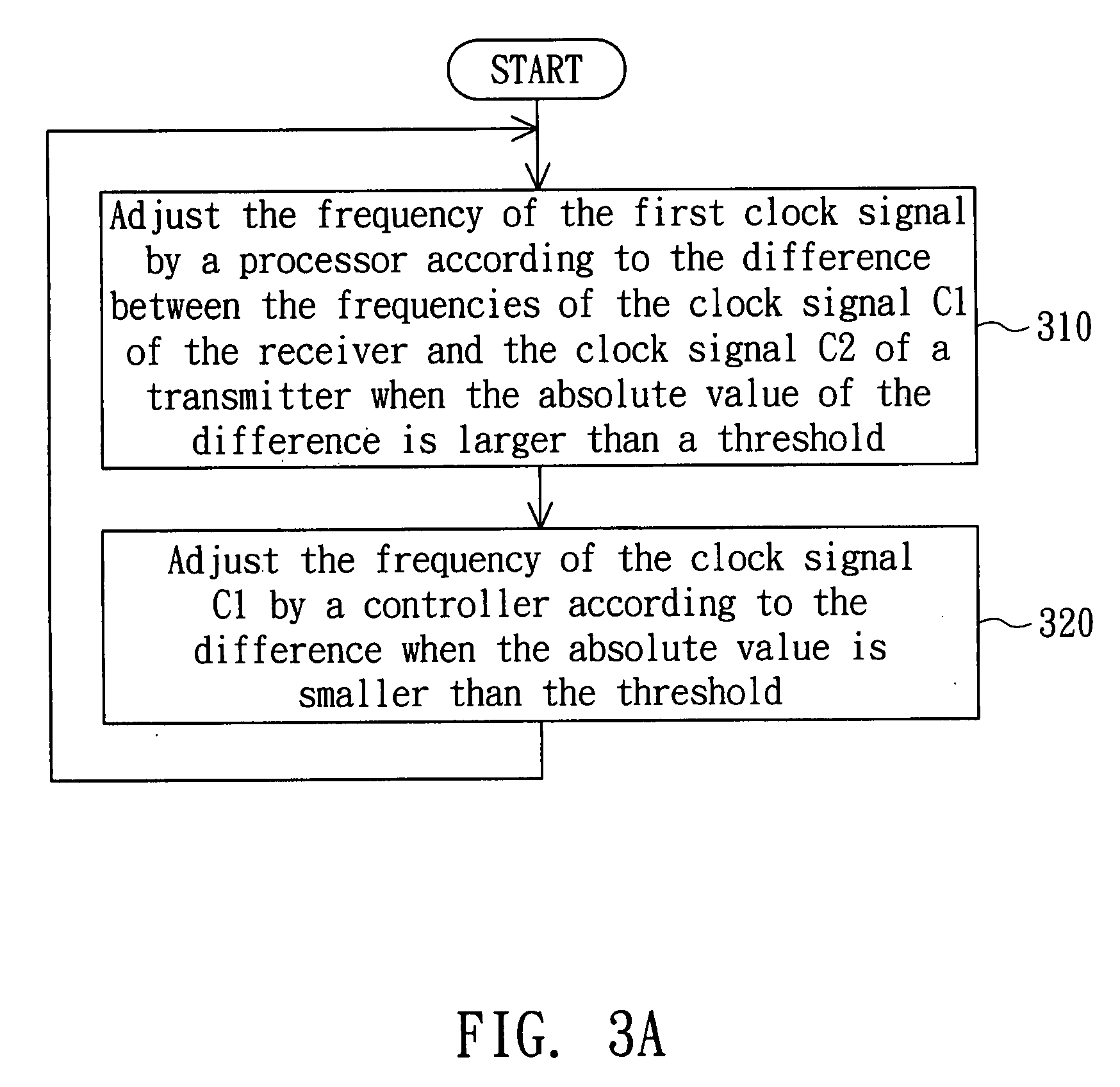
[0015]FIG. 2 shows a block diagram of the receiver 200 according to anther embodiment of the invention. The frequency of the clock signal C1 generated by the receiver 200 is adjusted to be close to the frequency of the clock signal C2 (not shown) of a transmitter, so that the receiver 200 could receive and decode the data from the transmitter correctly.
[0016]The receiver 200 includes a processor 210, a controller 220, and a clock generator 230. When an absolute value of a curre...
PUM
 Abstract
Description
Claims
Application Information
 - R&D
- Intellectual Property
- Life Sciences
- Materials
- Tech Scout
- Unparalleled Data Quality
- Higher Quality Content
- 60% Fewer Hallucinations
Browse by: Latest US Patents, China's latest patents, Technical Efficacy Thesaurus, Application Domain, Technology Topic, Popular Technical Reports.
© 2025 PatSnap. All rights reserved.Legal|Privacy policy|Modern Slavery Act Transparency Statement|Sitemap|About US| Contact US: help@patsnap.com


