Method of pre-exposing relief image printing plate

a relief image and printing plate technology, applied in the field of pre-exposing relief image printing plate, can solve the problems of physical limitations of the process of creating relief image in the plate, the difficulty of maintaining lines and even text using flexographic printing plate, and the difficulty of printing small graphic elements such as fine dots on flexographic pla

Inactive Publication Date: 2009-02-12
MACDERMID PRINTING SOLUTIONS
View PDF19 Cites 34 Cited by
  • Summary
  • Abstract
  • Description
  • Claims
  • Application Information

AI Technical Summary

Benefits of technology

[0029]It is an object of the present invention to provide an improved means for pre-exposing flexographic printing elements to remove oxygen from the photosensitive layer prior to imagewi...

Problems solved by technology

While the quality of articles printed using flexographic plates has improved significantly as the technology has matured, physical limitations related to the process of creating a relief image in a plate remain.
In particular, it is very difficult to print small graphic elements such as fine dots, lines and even text using flexographic printing plates while maintaining open reverse text and shadows.
Maintaining small dots on flexographic plates can be very difficult due to the nature of the platemaking process.
The smallest of these dots are prone to being removed during processing, which means no ink is transferred to these areas during printing (the dot is not “held” on plate and/or on press).
Alternatively, if the dot survives processing they are susceptible to damage on press.
For example small dots often fold over and/or partially break off during printing causing either excess ink or no ink to be transferred.
Flexo plates are typically not manufactured in an oxygen-free environment and are not coated or packaged in any way to rigoro...

Method used


Image

  • Method of pre-exposing relief image printing plate
  • Method of pre-exposing relief image printing plate

Examples


Embodiment Construction

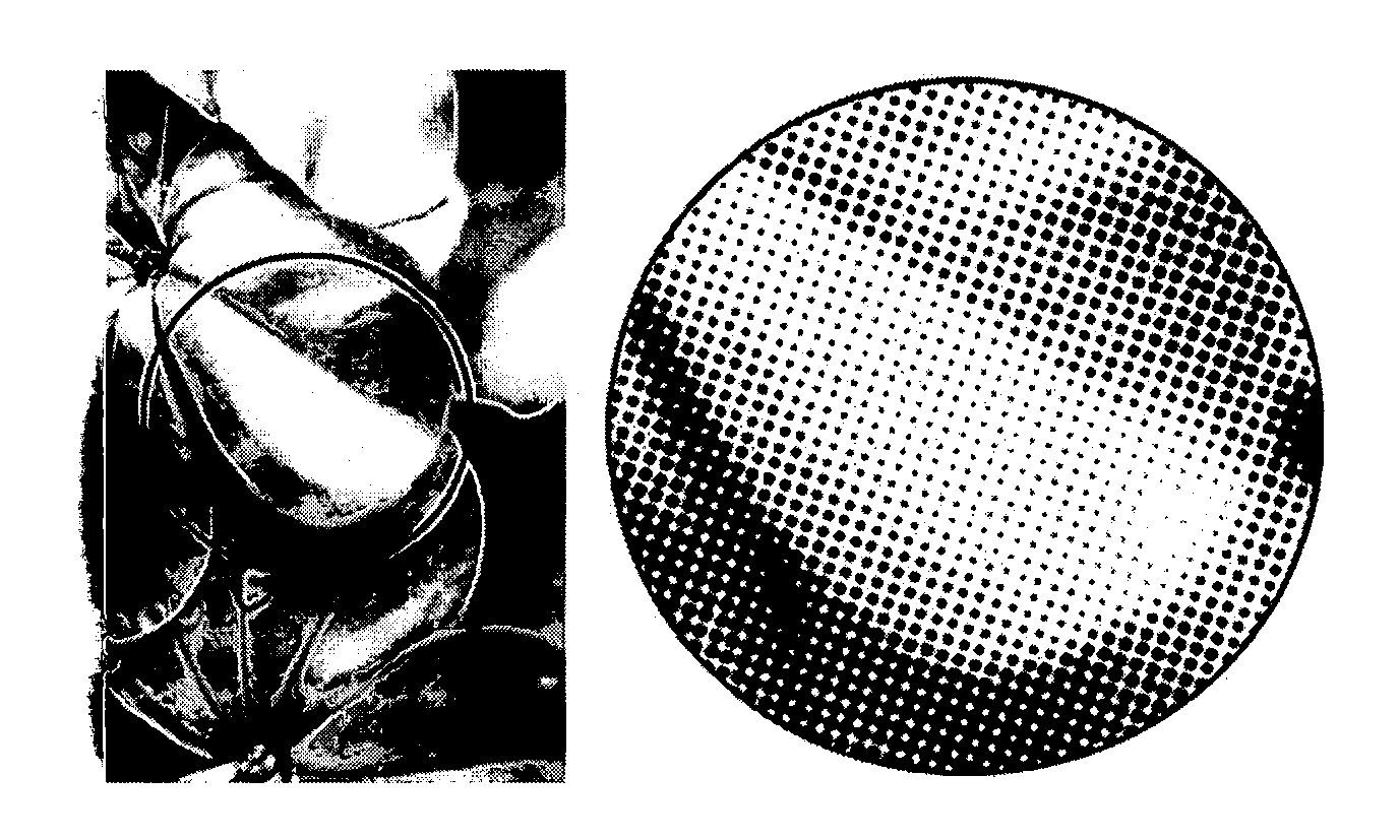
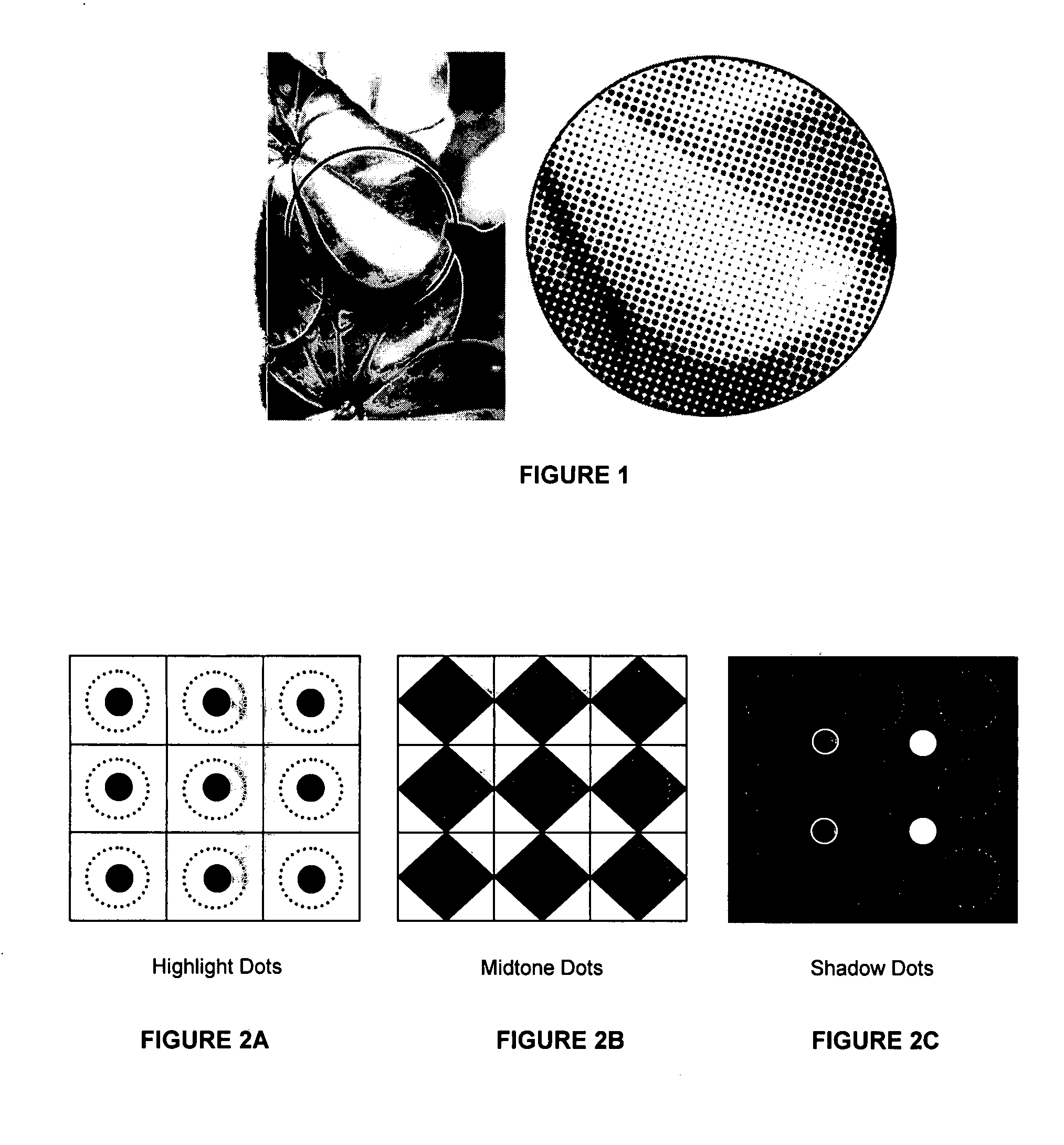
[0035]The inventors have surprisingly discovered that an improved relief image printing element can be obtained when the bump exposure is selectively (preferentially) applied to the photosensitive substrate using a screen tint which is matched to and registered with the image. In one embodiment, the printing element is processed in a CTP device.

[0036]Shadow tones decrease with increasing bump exposure, while holding the main exposure constant. This demonstrates that shadow tones fill in when the bump dose is increased. Thus, in order to achieve a better printing surface, i.e., with less fill-in of shadow tones and thus greater definition on the printing surface, the inventors have developed a process for selectively pre-exposing the printing element instead of pre-exposing the entire printing surface as is traditionally done in the prior art.

[0037]For example, U.S. Pat. No. 5,455,416 to Zertani et al., herein incorporated by reference in its entirety, describes a pre-exposure device...


PUM


Abstract

The present invention is directed to a method of selectively pre-exposing a photosensitive printing element prior to imagewise exposure in order to remove oxygen from the photosensitive layer prior to imagewise exposure. The invention is usable in a computer-to-plate process to produce flexographic relief image printing elements.

Description

FIELD OF THE INVENTION[0001]The present invention is directed to methods for selectively pre-exposing photosensitive printing elements prior to imagewise exposure.BACKGROUND OF THE INVENTION[0002]Flexographic printing is a method of direct rotary printing that uses a resilient relief image in a plate of rubber or photopolymer to print articles such as cartons, bags, labels or books. Flexographic printing is widely used in the production of newspapers and in the decorative printing of packaging media. Photosensitive printing plates and cylindrical printing sleeves have been developed to meet the demand for fast, inexpensive processing and long press runs.[0003]While the quality of articles printed using flexographic plates has improved significantly as the technology has matured, physical limitations related to the process of creating a relief image in a plate remain. In particular, it is very difficult to print small graphic elements such as fine dots, lines and even text using flex...

Claims


Application Information

Patent Timeline
IPC IPC(8): G03F7/00G03F1/88
CPCB41C1/00G03F7/2055G03F7/2022B41N1/12
Inventor ROBERTS, DAVID H.MARKHART, GARY T.
Owner MACDERMID PRINTING SOLUTIONS
Why Eureka
Try Eureka