
Electrical system for office furniture

a technology for electrical systems and office furniture, applied in the direction of applications, basic electric elements, connection contact material, etc., to achieve the effect of convenient adjustment and efficient housing of electrical components

Inactive Publication Date: 2009-02-12
KIMBALL INTERNATIONAL
View PDF29 Cites 39 Cited by
  • Summary
  • Abstract
  • Description
  • Claims
  • Application Information

AI Technical Summary

Benefits of technology

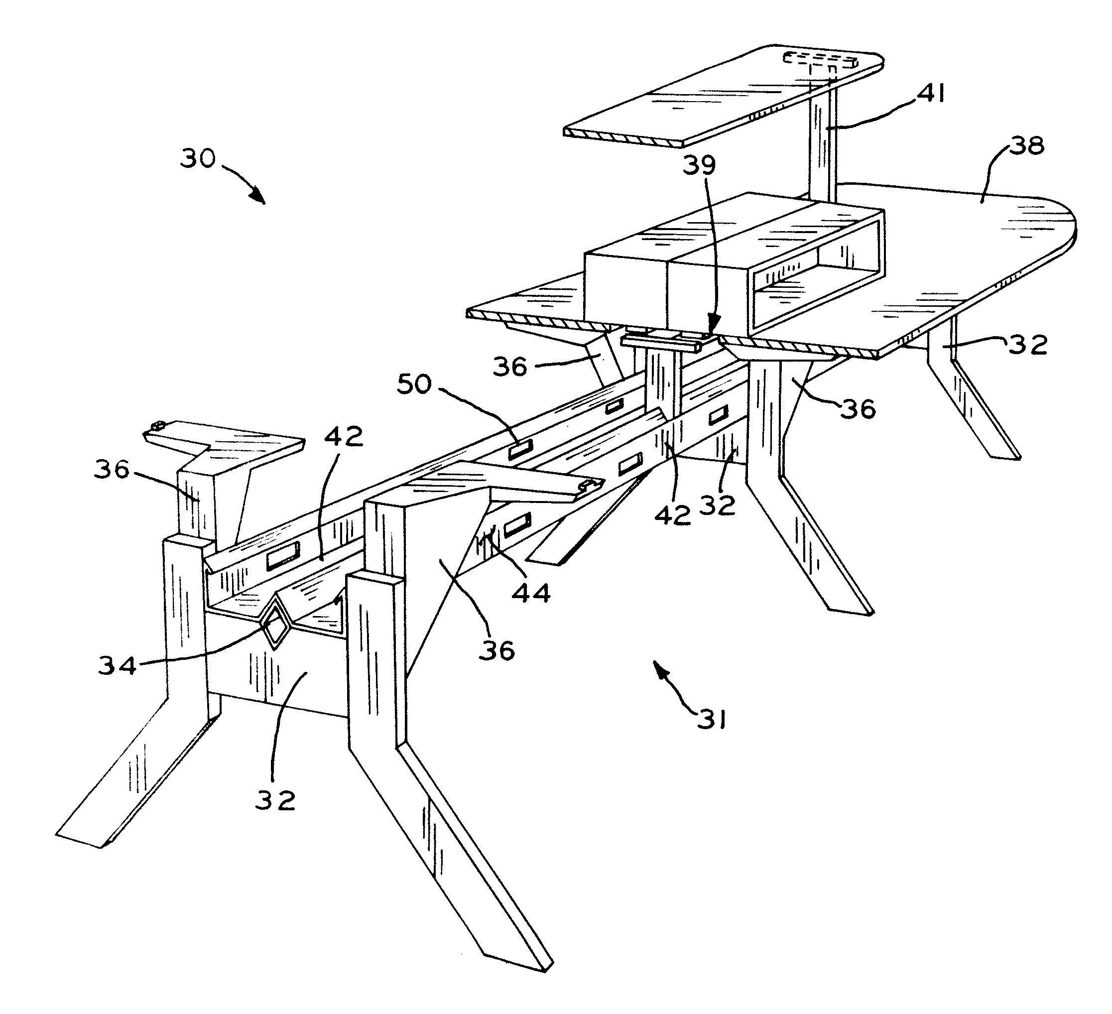
[0010]The present invention provides an article of furniture having a construction adapted to efficiently accommodate electrical components. The article of furniture includes a frame or chassis having support leg assemblies, and a beam connected to the support leg assemblies to which a channel is mounted. The support leg assemblies include work surface supports which support work surfaces at adjustable heights above the channel, and a gap between the work surfaces allows access to the electrical system within the channel. The electrical system is modular in design, and includes a series of components that may be connected to one another in a manner that the location of electrical outlet modules may be easily adjusted. The channel has a plurality of knock-out openings which may be selectively used for locating electrical outlets at any desired position along the channel.
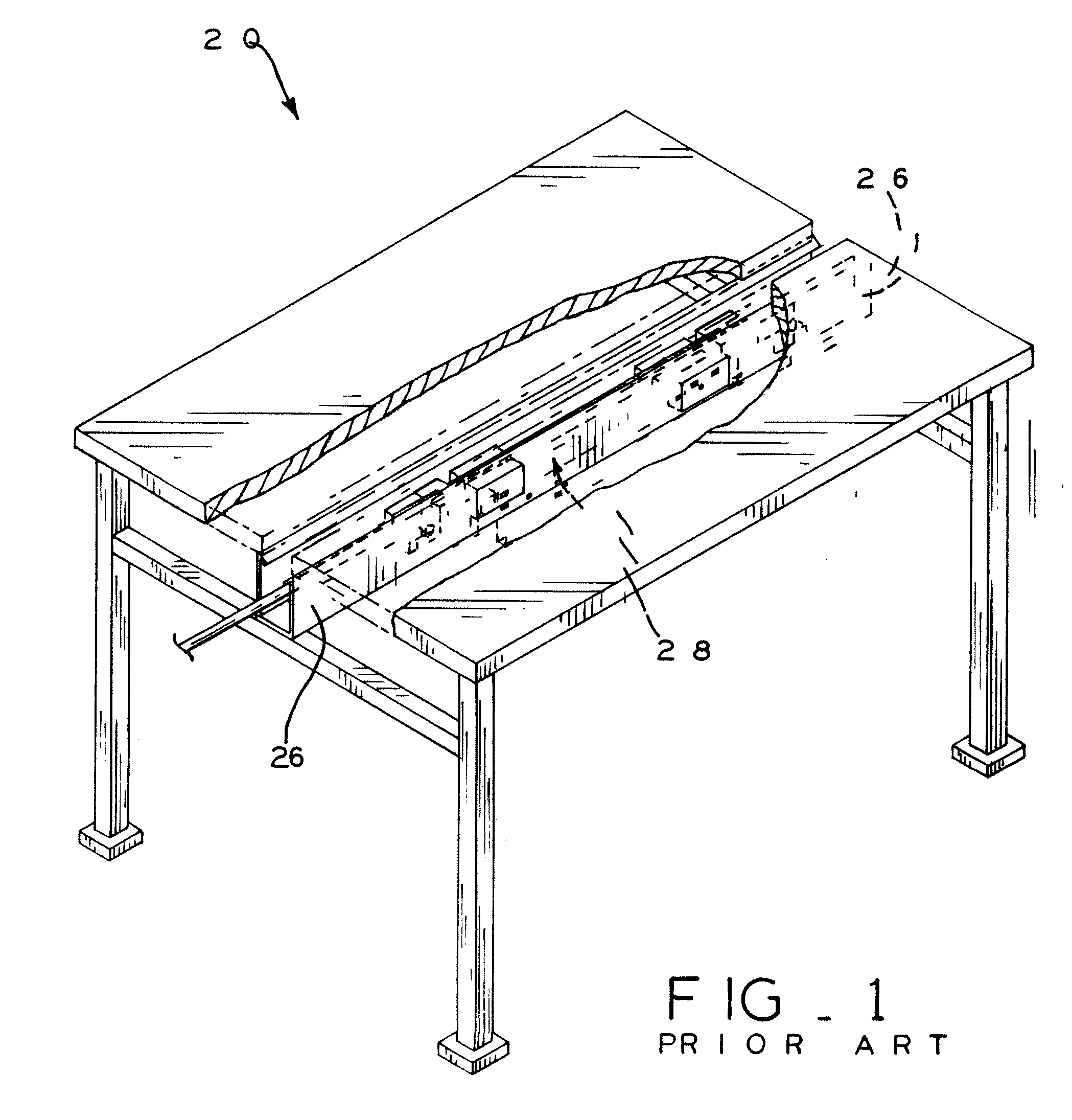
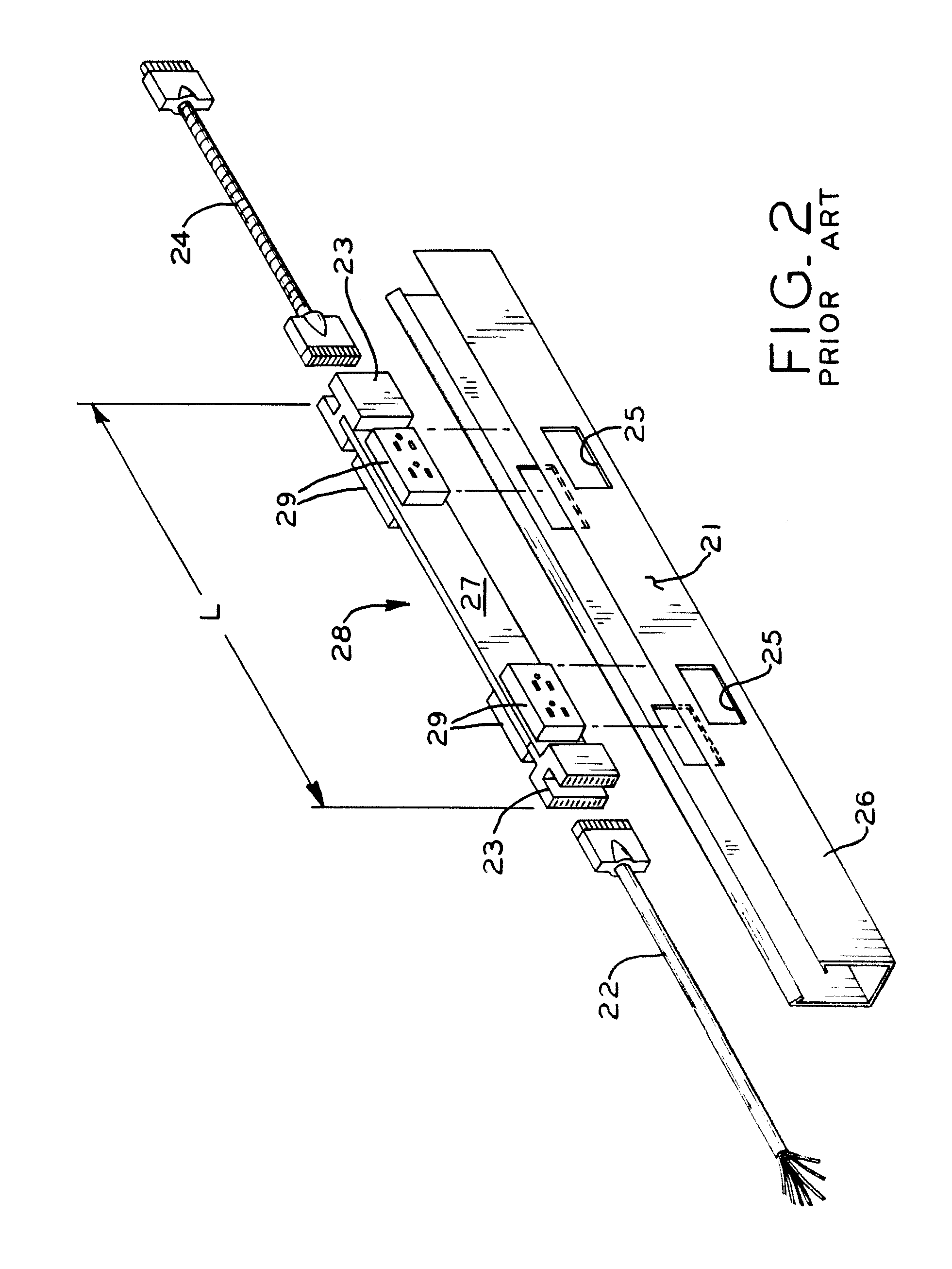
[0011]Advantageously, the present invention eliminates the need for using a known electrical harnesses assembly of the type described above and shown in FIGS. 1 and 2, in favor of a relatively wider channel that may incorporate a modular electrical system including components that may be selectively configured to place electrical and / or data outlets in locations desired by the user. The relatively wider channel allows electrical and / or data outlets to be placed beneath the work surface of the table at locations nearer the user, allowing easier access, and also facilitates easy installation of the electrical assembly, which may be laid into the channel freely with only the electrical and / or data outlets connected to the knock-out openings in the channel.
[0012]A method for forming the knock-out openings in the channel is also disclosed, in which the knock-out portions are first stamped in a flat metal sheet that will eventually be formed into the channel. In particular, the knock-out portions are partially separated from the sheet and displaced from the plane of the sheet using a punch and die. In the subsequent forming process by which the channel is formed form the sheet, the knock-out portions are pressed substantially back into the plane of the sheet itself by a bending die, with the result that the knock-out portions may be easily separated from the knock out openings while the periphery of the knock-out portions is visually disguised, such that even though the channel is formed with knock-out openings, the surface of the channel visually appears substantially smooth and uninterrupted.

Problems solved by technology

Other municipalities do not permit such extension cords and instead require that power supplies to the electrical outlets be fully contained and not connected via extension cords.

Method used


Image

  • Electrical system for office furniture
  • Electrical system for office furniture
  • Electrical system for office furniture

Examples


Embodiment Construction

[0043]Referring to FIG. 3, an article of office furniture is shown as a desking system 30, but may also be formed as a table, a partition system, or any other article of furniture. Desking system 30 includes a support frame or chassis 31 having at least a pair of leg assemblies 32 and a horizontally-disposed beam 34 connecting leg assemblies 32. A horizontally-disposed channel 42 is mounted to beam 34, and is discussed in detail below. A plurality of work surface supports 36 are connected to leg assemblies 32, and support a plurality of work surfaces 38 above leg assemblies 32 at locations disposed vertically upwardly from channel 42. Work surfaces 38 are shown only in the upper right portion of FIG. 3 such that frame 31 is visible therebeneath, it being understood that frame 31 would normally support work surfaces 38 positioned at the lower left portion is FIG. 3 on work surface supports 36. The rear edges of work surfaces 38 may define a gap 39 therebetween which is disposed above...


PUM

PropertyMeasurementUnit
electrical poweraaaaaaaaaa
flexibleaaaaaaaaaa
distanceaaaaaaaaaa

Abstract

An article of furniture having a construction adapted to efficiently accommodate electrical components. The article of furniture includes a frame or chassis having support leg assemblies, and a beam connected to the support leg assemblies to which a channel is mounted. The support leg assemblies include work surface supports which support work surfaces at adjustable heights above the channel, and a gap between the work surfaces allows access to the electrical system within the channel. The electrical system is modular in design, and includes a series of components that may be connected to one another in a manner that the location of electrical outlet modules may be easily adjusted. The channel has a plurality of knock-out openings which may be selectively used for locating electrical outlets at any desired position along the channel.

Description

CROSS-REFERENCE TO RELATED APPLICATIONS [0001]This application claims the benefit under Title 35, U.S.C. §119(e) of U.S. Provisional Patent Application Ser. No. 60 / 954,582, entitled ELECTRICAL SYSTEM FOR OFFICE FURNITURE, filed on Aug. 8, 2007, the disclosure of which is expressly incorporated by reference herein in its entirety.BACKGROUND[0002]1. Field of the Invention[0003]The present invention relates to the management of electrical and / or communication cables associated with an article of furniture, such as, for example, an article of office furniture.[0004]2. Description of the Related Art[0005]Articles of office furniture, such as tables, are often used in environments which require electrical outlets and / or communication outlets near a work surface, such that a user may plug an electrical cord into the electrical outlet to power a device positioned on or proximate the article of furniture, or may plug a communication cable into the communication outlet to provide data service...

Claims


Application Information

Patent Timeline
Patent Type & Authority Applications(United States)
IPC IPC(8): H02G3/00B21D31/00
CPCA47B21/06Y10T29/49826Y10T29/49879
Inventor HENRIOTT, JAY M.CRAFTON, DAVID B.
Owner KIMBALL INTERNATIONAL
Learn More