Joint structure for vehicle body members

Active Publication Date: 2005-06-30
KOBE STEEL LTD
View PDF1 Cites 27 Cited by
  • Summary
  • Abstract
  • Description
  • Claims
  • Application Information

AI Technical Summary

Benefits of technology

[0007] It is an object of the present invention, therefore, to provide a joint structure for vehicle

Problems solved by technology

The above-described joint structure for dissimilar metals, however, has encountered the following problem: During joining, such as mechanical joining, or during baking in a painting step, distortion at a site

Method used


Image

  • Joint structure for vehicle body members
  • Joint structure for vehicle body members
  • Joint structure for vehicle body members

Examples


Embodiment Construction

[0014] A joint structure for vehicle body members according to the present invention will now be described in detail by an embodiment with reference to the accompanying drawings, but the invention is not limited by this embodiment.

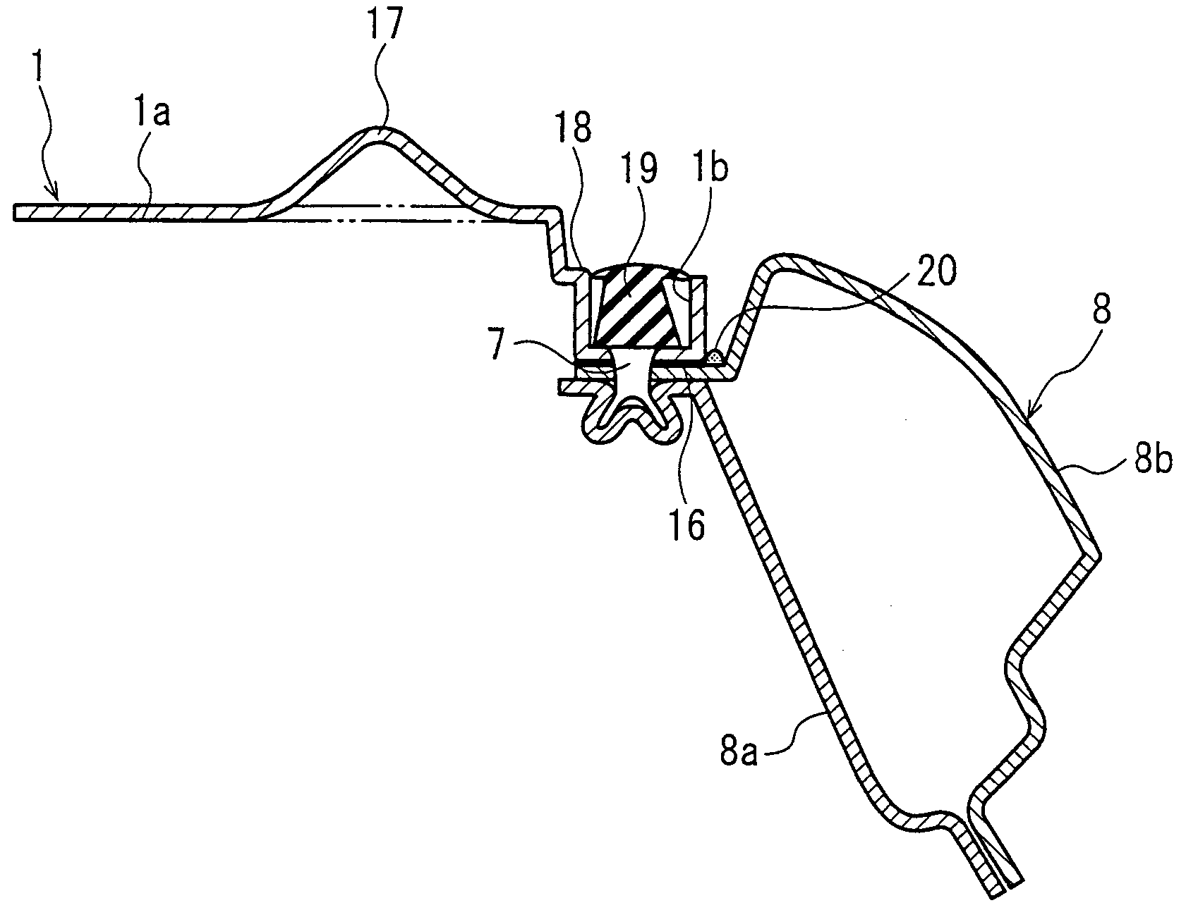
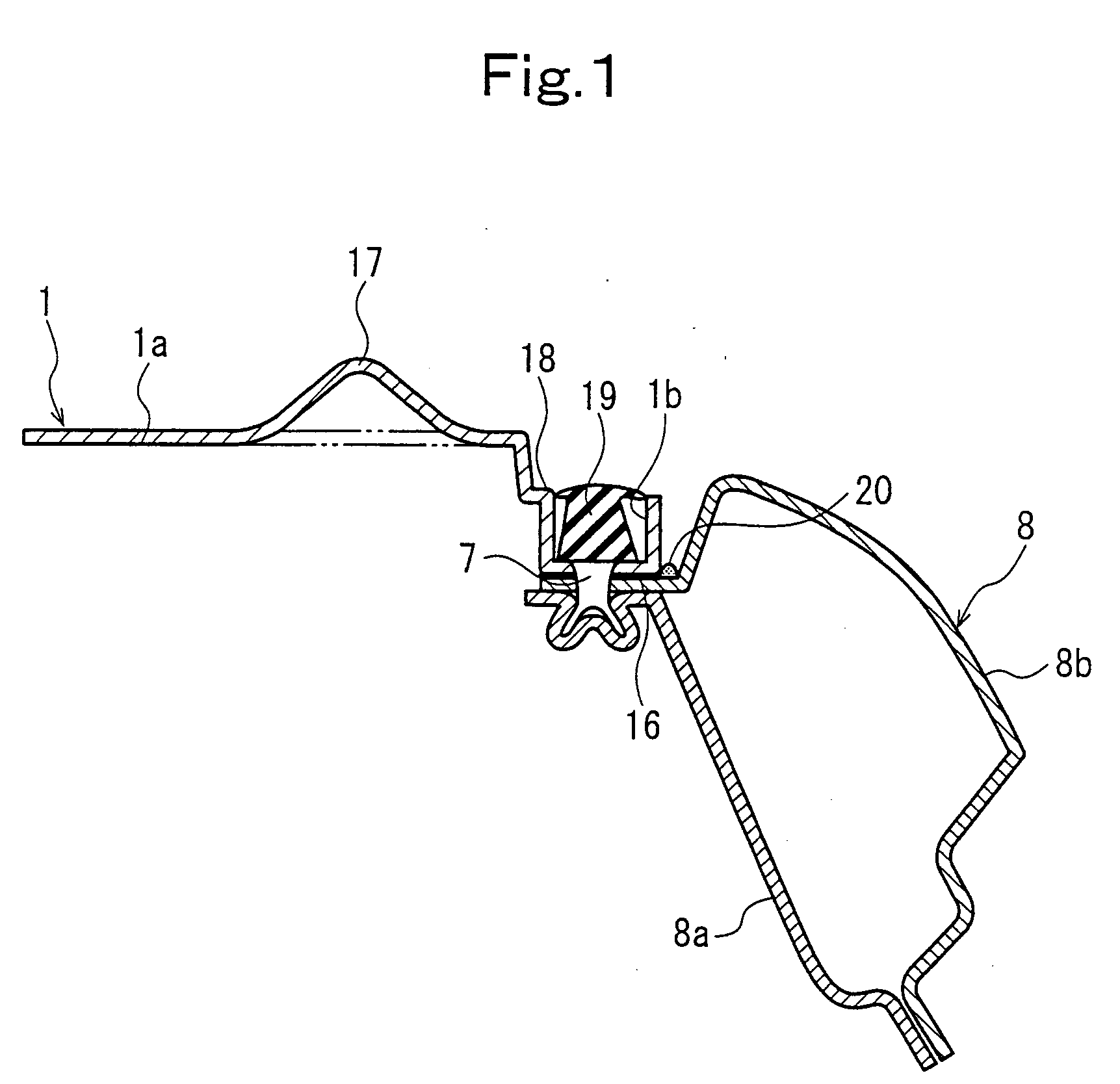
[0015]FIG. 1 is a sectional view of a junction between an aluminum roof panel and a side structure showing an embodiment of the present invention. FIG. 2 is a plan view of the aluminum roof panel. FIG. 3 is an explanation drawing showing the step of mounting the aluminum roof panel.

[0016] As shown in FIGS. 2 to 3, an aluminum roof panel 1, which is a structure constituting a part of a monocoque body, is subassembled to a front roof rail 2, a rear roof rail 3, a front roof bow 4, and a rear roof bow 5, each made of steel (steel plate), by mechanical joining using non-piercing rivets 7 or the like, with a sealant 6 or the like being interposed, as appropriate, between their joining surfaces. At the time of the subassembly, a map lamp bracket 13 and sun vis...


PUM


Abstract

To provide a joint structure for vehicle body members, which can effectively accommodate distortion due to joining of dissimilar metals, a joining surface of an aluminum roof panel and a joining surface of a side roof rail made of steel are joined by non-piercing rivets, with an electrically insulating structural adhesive being interposed between the joining surfaces, and a bead extending along the joining surfaces is formed in the aluminum roof panel.

Description

CROSS REFERENCE TO RELATED APPLICATION [0001] The entire disclosure of Japanese Patent Application No. 2003-358874 filed on Oct. 20, 2003, including specification, claims, drawings and summary, is incorporated herein by reference in its entirety. BACKGROUND OF THE INVENTION [0002] 1. Field of the Invention [0003] This invention relates to a joint structure for vehicle body members comprising dissimilar metals in a vehicle such as an automobile. [0004] 2. Description of the Related Art [0005] In recent years, vehicle body members made of aluminum or an aluminum alloy (for example, aluminum roof panel) have been utilized for achieving the weight reduction of a vehicle body in a vehicle such as an automobile. In joining a vehicle body member made of aluminum and a vehicle body member made of steel, metallurgical joining (melt bonding such as spot welding) is not employed, since the aluminum and the steel are dissimilar metals, and their physical properties, such as melting point and co...

Claims


Application Information

Patent Timeline
IPC IPC(8): B62D25/06B62D25/07B62D27/00B62D65/06
CPCB62D27/00B62D25/07
Inventor OGAWA, SHINICHIMATSUMURA, YOSHINOBUUCHIDA, KOSAKU
Owner KOBE STEEL LTD
Why Eureka
Try Eureka