
Motor cycle with fuel cell and stack structure of fuel cell

Inactive Publication Date: 2006-11-09
HONDA MOTOR CO LTD
View PDF4 Cites 25 Cited by
  • Summary
  • Abstract
  • Description
  • Claims
  • Application Information

AI Technical Summary

Benefits of technology

[0028] One or more embodiments of the present invention provide a motorcycle mounted with a fuel cell in which a center of gravity of the motorcycle is located right below a seat so as to improve a foot setting property at the time of traveling and a foot setting property at the time of stop.
[0029] In addition, one or more embodiments of the present invention provide a stack structure of a fuel cell which can efficiently accommodating a power-generation cell stack.
[0030] Moreover, one or more embodiments of the present invention provide a fuel cell vehicle which can stabilize power generation amount of a fuel cell with a low-cost structure by adjusting an opening ratio of a flow passage with high precision so as to accurately control an internal pressure of the fuel cell.

Problems solved by technology

Thus, the motorcycle requires a considerable space for mounting the large-sized fuel cell.
Accordingly, it is difficult to improve a foot comfort.
As a result, the pressure between the power-generation cells is not uniform, thereby deteriorating power-generation efficiency.
However, in the throttle valve disclosed in JP-A-11-343878, since the amount of rotation of the rotation axis is detected by the potentiometer, the detection signal is an analog signal and thus electrical noise can be added thereto.
Accordingly, when the valve disclosed in JP-A-11-343878 is adopted for the fuel cell system disclosed in JP-A-09-259912, it is difficult to accurately control the internal pressure of the fuel cell, thereby varying the power generation amount of the fuel cell.

Method used


Image

  • Motor cycle with fuel cell and stack structure of fuel cell
  • Motor cycle with fuel cell and stack structure of fuel cell
  • Motor cycle with fuel cell and stack structure of fuel cell

Examples


first exemplary embodiment

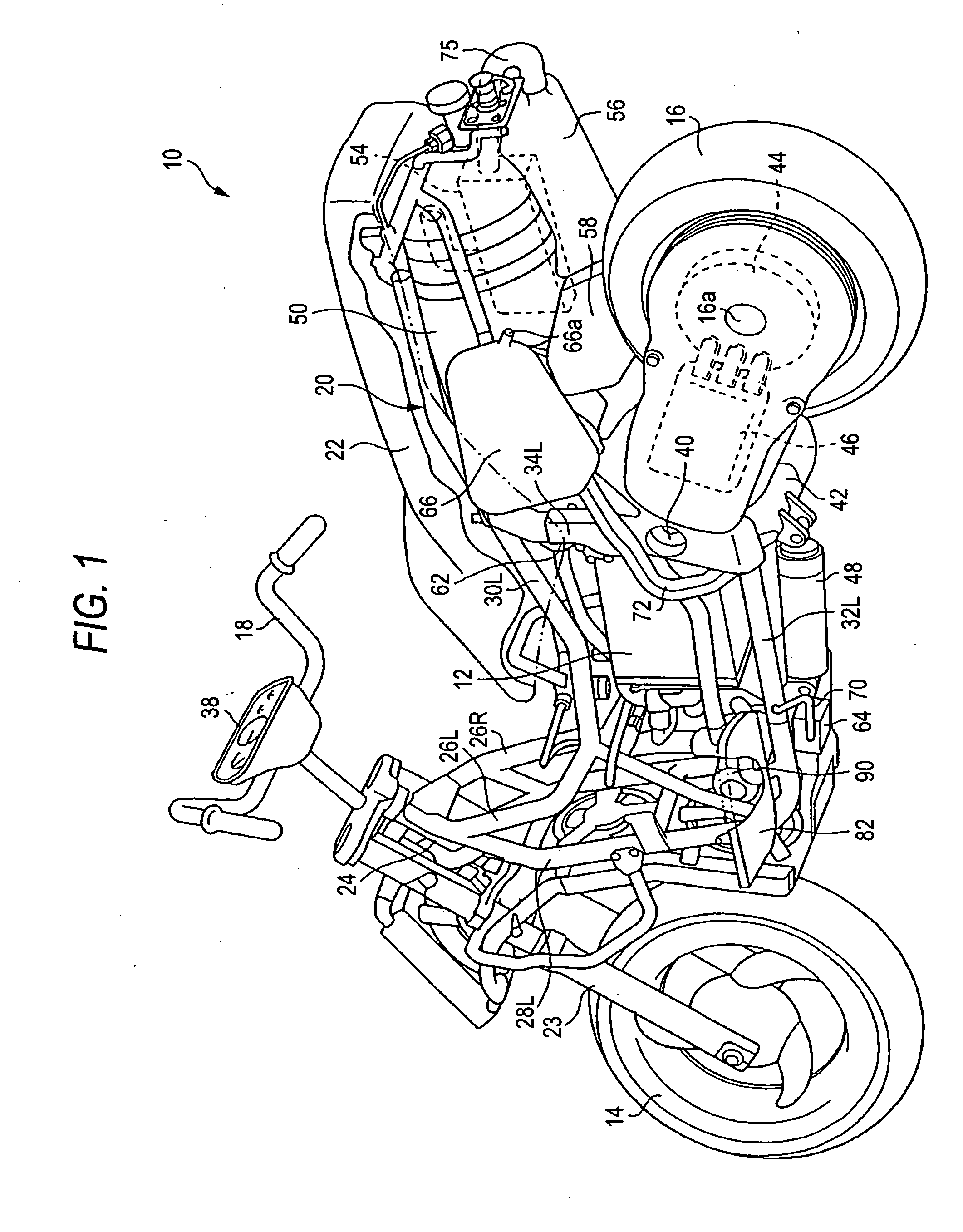
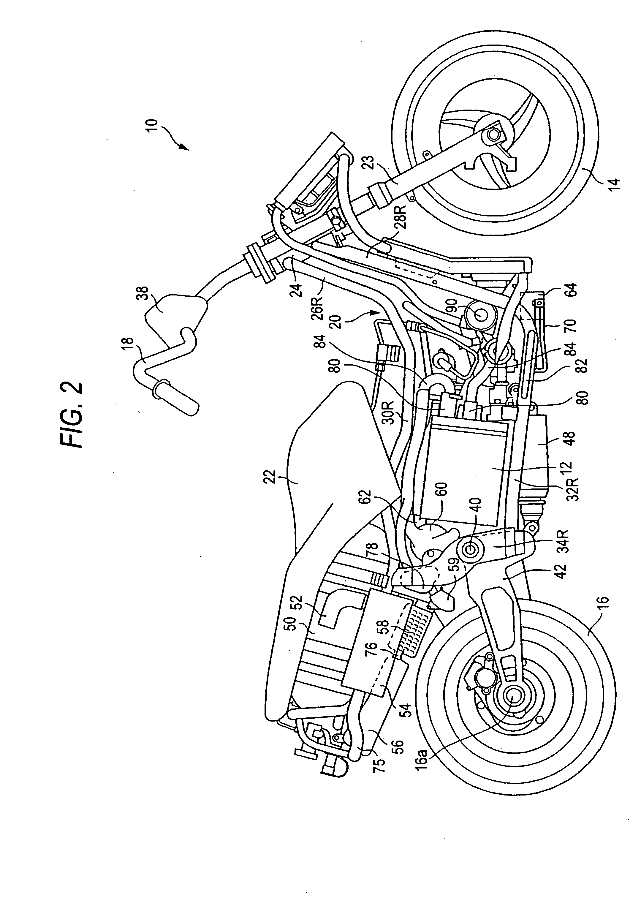
[0121]FIG. 1 is a perspective view illustrating a motorcycle according to an exemplary embodiment of the present invention as seen from a rear side, where a scooter-type motorcycle is exemplified. FIG. 2 is a side view of the motorcycle shown in FIG. 1 and FIG. 3 is a schematic plan view of the motorcycle shown in FIG. 1.

[0122] In FIGS. 1 to 3, the motorcycle 10 includes a fuel cell 12 and travels by the use of power obtained from the fuel cell 12. The fuel cell 12 generates power by allowing a fuel gas (hydrogen gas) supplied to an anode to react with a reactant gas (air) supplied to a cathode. In an embodiment, since a known fuel cell is employed as the fuel cell 12, detailed description thereof will be omitted.

[0123] The motorcycle 10 includes a front wheel 14 as a steering wheel, a rear wheel 16 as a driving wheel, a handle bar 18 connected to the front wheel 14 so as to steer the traveling direction of the motorcycle 10, a frame 20, and a seat 22 which is disposed in a rear s...

second exemplary embodiment

[0160] In the following description, directions such as a longitudinal direction and a lateral direction are equal to those of a vehicle if there is no specific description. In the drawings, arrow FR denotes a forward direction of a motorcycle, arrow LH denotes a left direction of the motorcycle, and arrow UP denotes an upward direction.

[0161] A motorcycle 101 shown in FIGS. 8 to 10 is a fuel cell vehicle which travels by driving a motor 131 for driving the vehicle by the use of power supplied from a fuel cell unit 151 mounted at the approximate center of the vehicle body. The motorcycle 101 is of a stator type having a bottom floor portion (hereinafter, simply referred to as floor portion) in the vehicle body, where the fuel cell unit 151 is disposed in the vicinity of the floor portion 103 and the motor 131 as a so-called wheel motor is disposed inside a rear wheel 132 as a driving wheel of the motorcycle 101. The motor 131 is embodied as an integrated unit having a motor body an...

third exemplary embodiment

[0193] Hereinafter, a fuel cell vehicle according to an exemplary embodiment of the present invention will be described with reference to FIGS. 14 to 21.

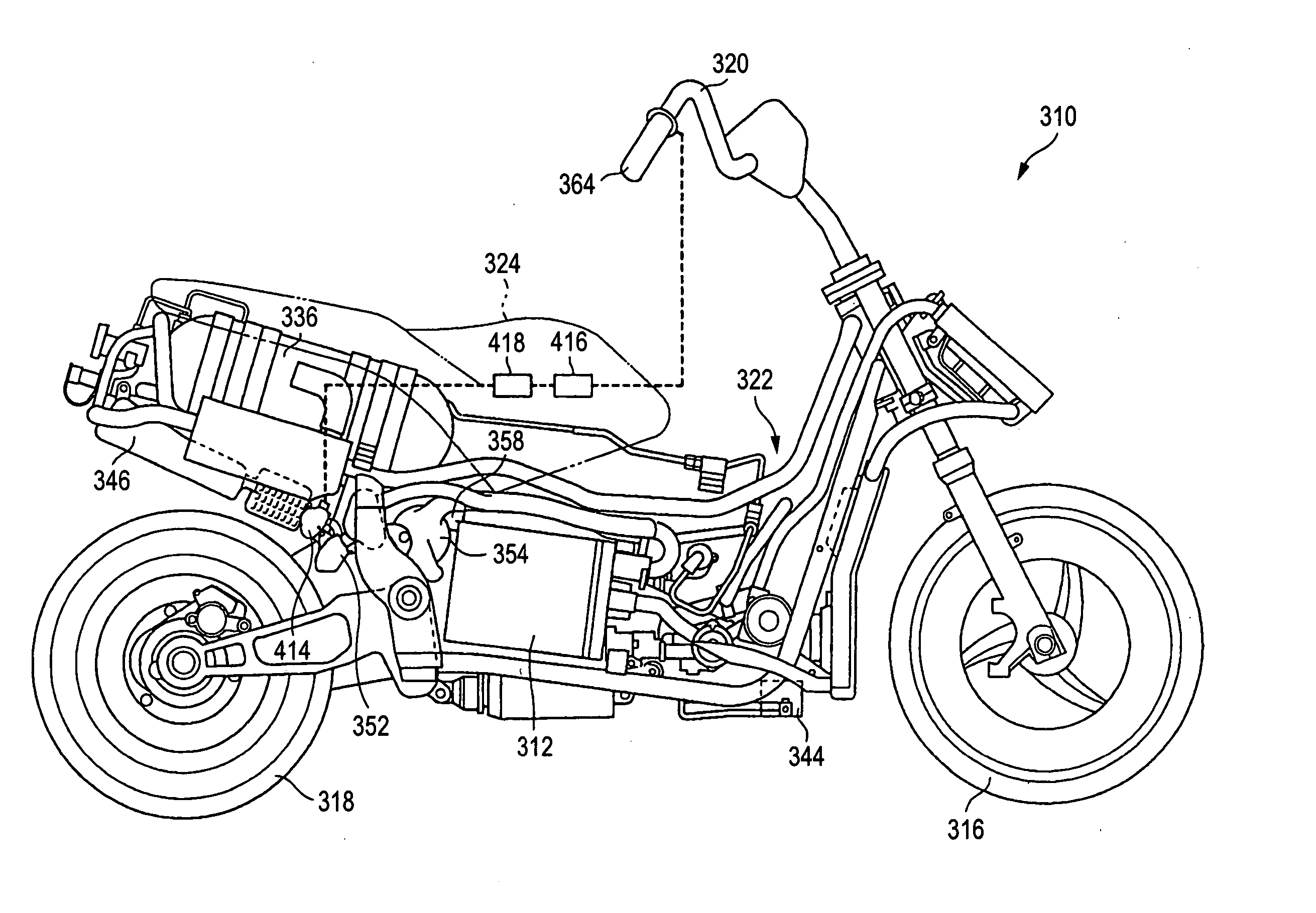
[0194] As shown in FIG. 14, a fuel cell motorcycle 310 as the fuel cell vehicle according to the present exemplary embodiment has a fuel cell 312 mounted thereon and thus travels by driving a motor 314 by the use of power obtained from the fuel cell 312. The fuel cell 312 is a polymer electrolyte membrane fuel cell (PEMFC) in which a plurality of unit cells is stacked and generates electric power by reacting a reactant gas (air) supplied to a cathode with a fuel gas (hydrogen gas) supplied to an anode. The fuel cell motorcycle 310 includes a front wheel 316 as a steering wheel, a rear wheel 308 as a driving wheel, a handle 320 for steering the front wheel 316, a frame 322, and a seat 324 for allowing a driver and a passenger to sit.

[0195] A fuel cell system 326 of the fuel cell motorcycle 310, as shown in FIG. 15, includes reactan...


PUM


Abstract

The motorcycle is provided with a pipeline 84 for supplying at least hydrogen and oxygen. A fuel cell 12 is disposed below a seat 22 on which a driver sits. A connection port 80 between the fuel cell 12 and the pipe line 84 is disposed rearward of a foot step 82 on which the driver can set his foot. Accordingly, a space A necessary and sufficient for the foot step 82 is guaranteed, thereby improving a foot setting property at the time of traveling and a foot setting property at the time of stop.

Description

[0001] The present application claims foreign priority based on Japanese Patent Applications No. P. 2005-107708 filed on Apr. 4, 2005, No. P. 2005-136205 filed on May 9, 2005, and No. P. 2005-152784 filed on May 25, 2005, the contents of them are incorporated herein by reference. BACKGROUND OF THE INVENTION [0002] 1. Field of the Invention [0003] The present invention relates to a motorcycle mounted with a fuel cell. [0004] In addition, the present invention relates to a stack structure of a fuel cell in which a stacked body of power-generation cells is accommodated in a box-shaped casing, each power-generation cell having an electrolyte-electrode structure and a pair of separators between which the electrolyte-electrode structure is interposed. [0005] Moreover, the present invention relates to a fuel cell having a valve for adjusting a pressure of an exhaust gas generated through a reaction in a fuel cell. [0006] 2. Related Art [0007] Most of motorcycles use an internal combustion ...

Claims


Application Information

Patent Timeline
IPC IPC(8): H01M8/02B60L11/18B62J99/00
CPCB62K2202/00B62K2204/00H01M8/2475H01M8/248Y02E60/50H01M2008/1095H01M2250/20Y02T90/32H01M8/2485Y02T90/40B62K11/00H01M8/24B60L50/50
Inventor MAKUTA, YOHEIHORII, YOSHIYUKIIKUI, KUNIAKI
Owner HONDA MOTOR CO LTD
Learn More