Image Forming apparatus

a technology of image forming and forming parts, applied in mechanical devices, yielding couplings, couplings, etc., can solve the problems of uneven density, speed fluctuation of drive motors, image defects, etc., to reduce parts cost and production cost, prevent image defects, and improve size accuracy and attachment accuracy

Inactive Publication Date: 2009-02-12
RICOH KK +1
View PDF4 Cites 16 Cited by
  • Summary
  • Abstract
  • Description
  • Claims
  • Application Information

AI Technical Summary

Benefits of technology

[0010]The present invention is directing toward providing an image formation apparatus capable of rotating a developing roller at a constant speed while reducing the parts cost and the production cost.
[0012]According to the above-described image forming apparatus, because a constant velocity joint is used as the connection unit that connects the drive shaft provided in the apparatus body to the driven shaft of the unit removable from the apparatus body, even if an offset angle is formed between the drive shaft and the driven shaft, it is possible to rotate the driven shaft at a constant speed. Therefore, even if an offset angle is formed between the drive shaft and the driven shaft, the developing roller is prevented from being rotated unevenly, so that it is possible to prevent image defects such as uneven density in color images and monochrome (single color) images. Accordingly, without improving the size accuracy and the attachment accuracy of members supporting the drive shaft inside the apparatus body in order to prevent formation of an offset angle between the drive shaft and the driven shaft, it is possible to prevent uneven rotation of the developing roller and thus to reduce the parts cost and production cost.

Problems solved by technology

The variation in the transmitted torque at the drive force transmission unit negatively affects a drive motor (a drive source) (not shown), resulting in speed fluctuation of the drive motor.
This causes uneven rotation of the developing roller 242, resulting in image defects such as uneven density.
But this increases the parts cost and the production cost.

Method used


Image

  • Image Forming apparatus
  • Image Forming apparatus
  • Image Forming apparatus

Examples


Embodiment Construction

[0039]An electrophotographic printer (hereinafter referred to simply as a printer) as an image forming apparatus of an embodiment of the present invention is described below.

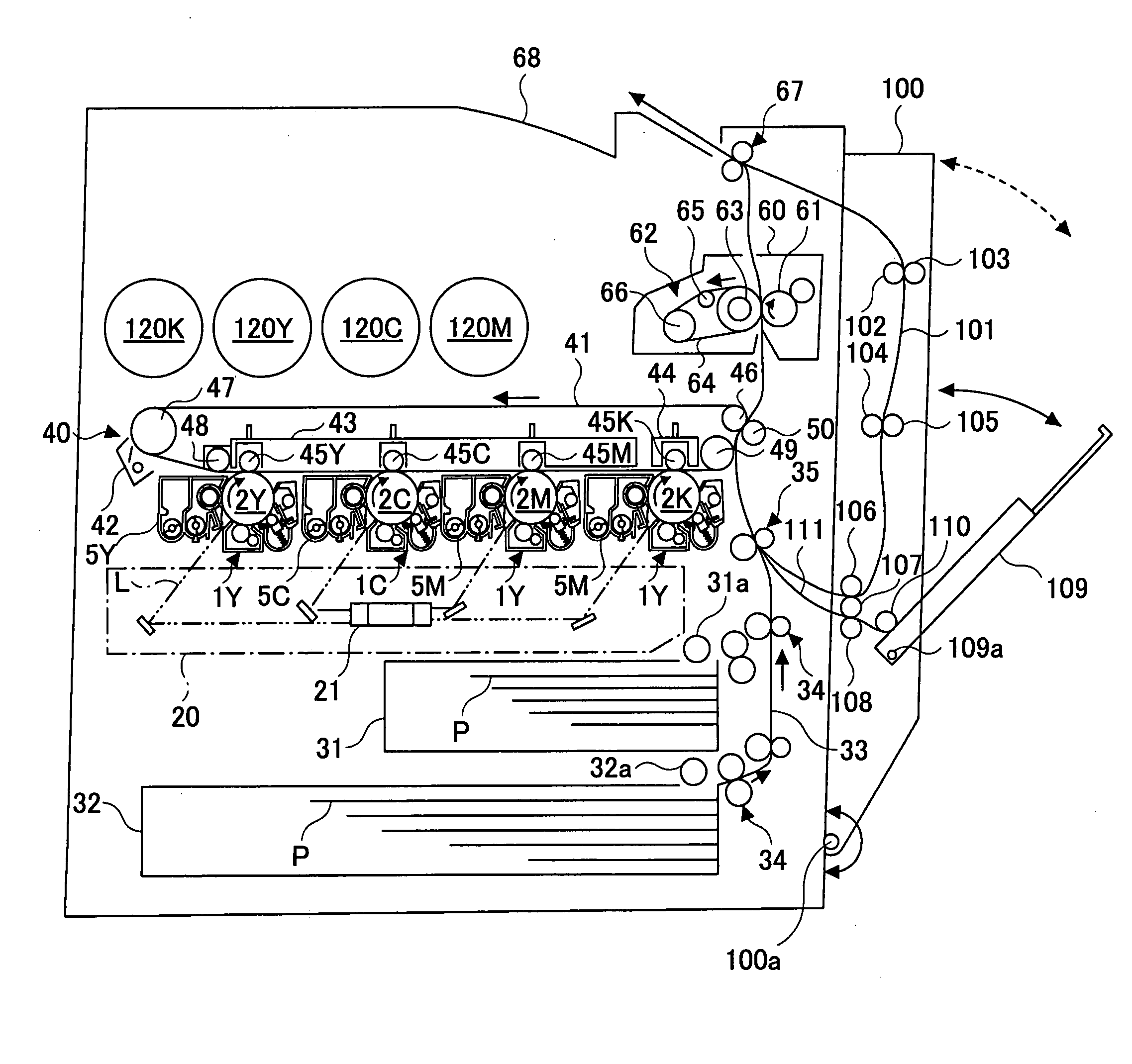
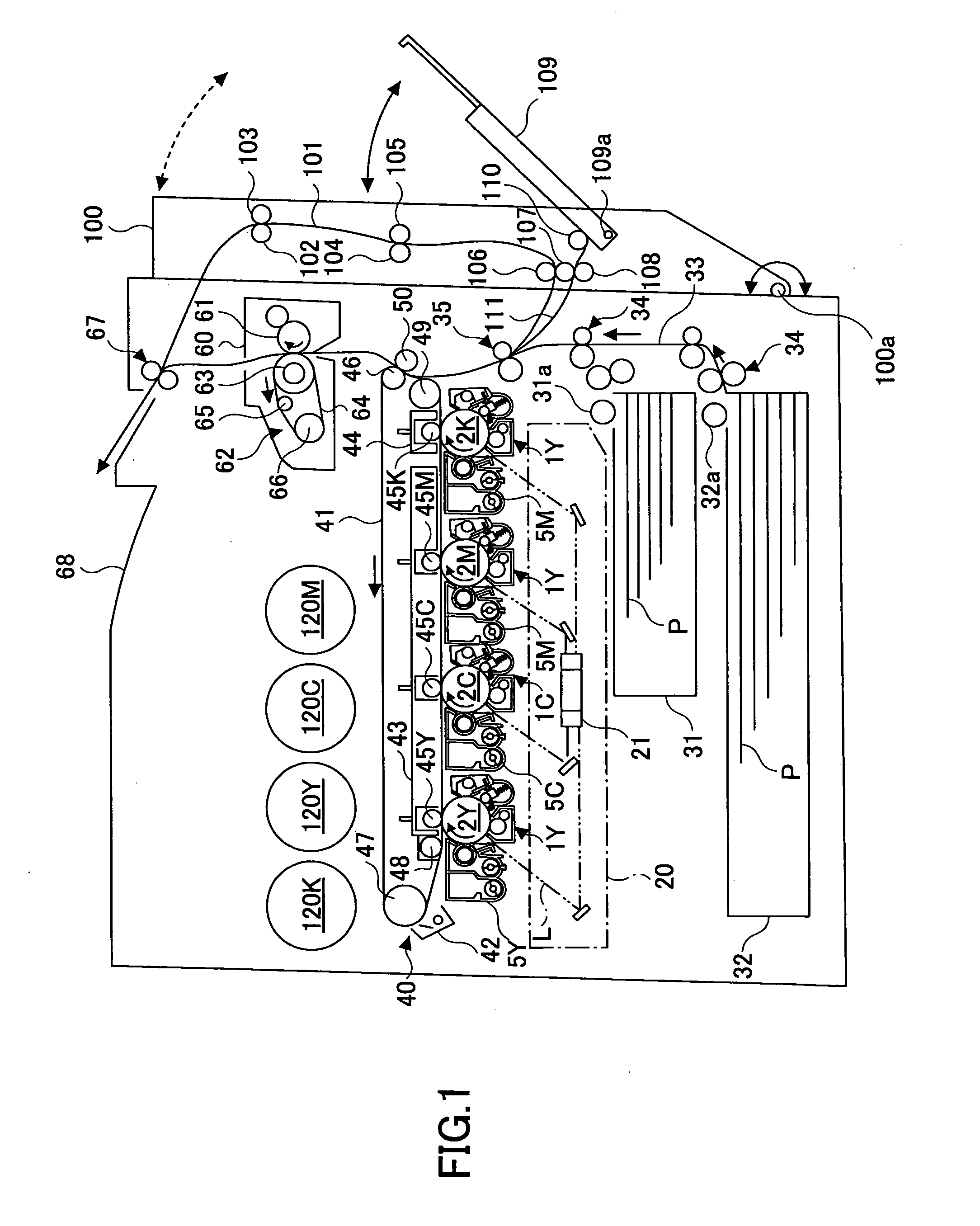
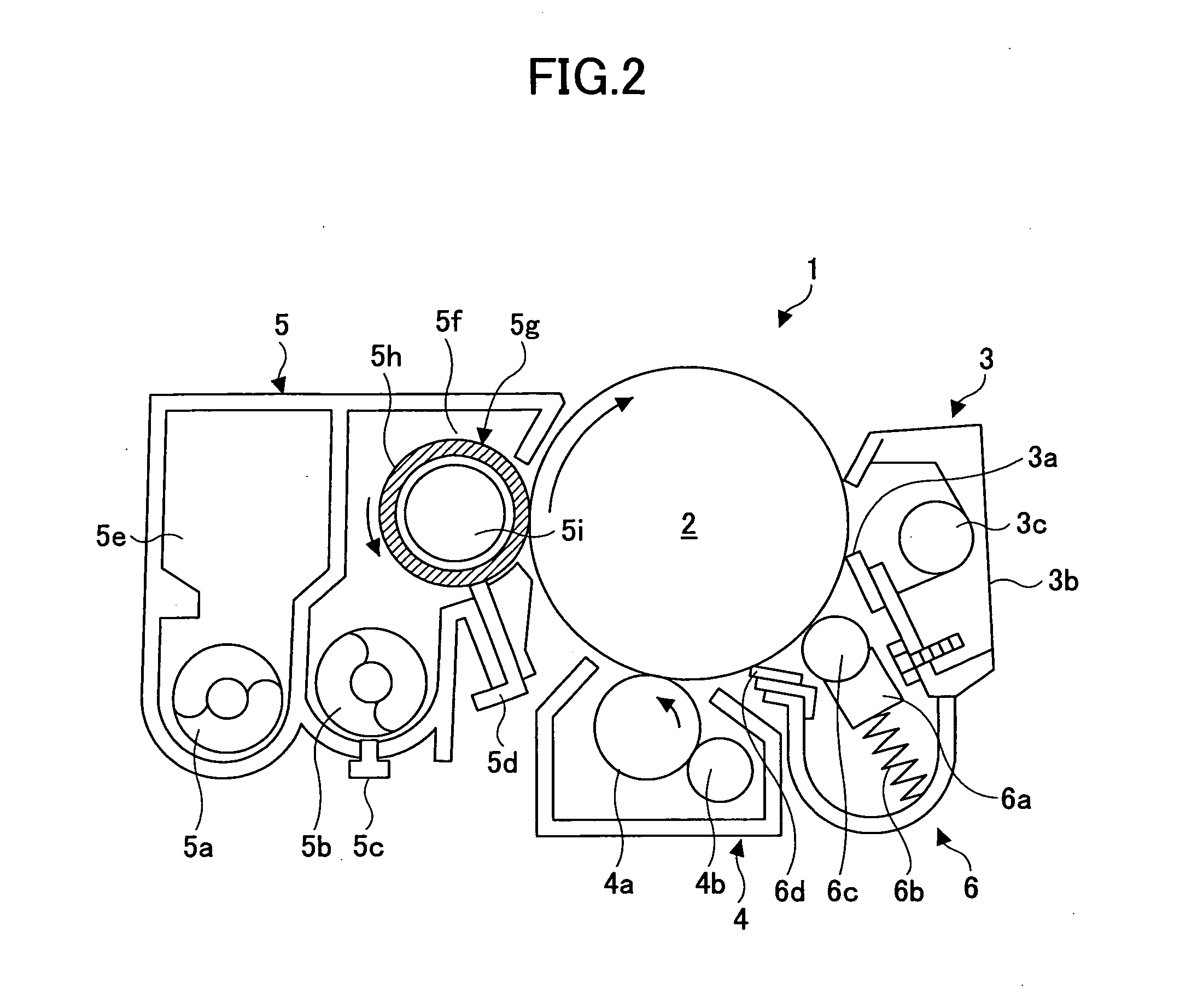
[0040]First, the basic configuration of the printer is described below. FIG. 1 is a schematic configuration diagram illustrating the printer. Referring to FIG. 1, the printer includes four process cartridges 1Y, 1C, 1M, and 1K for creating toner images of yellow, cyan, magenta, and black (hereinafter referred to as Y, C, m, and K, respectively), respectively. Although the process cartridges 1Y, 1C, 1M, and 1K use toners of different colors, namely, Y, C, M, and K, the process cartridges 1Y, 1C, 1M, and 1K have the same configuration. The process cartridges 1Y, 1C, 1M, and 1K are replaced when their service lives are over. It is to be noted that because the process cartridges 1Y, 1C, 1M, and 1K have the same configuration, their reference characters Y, C, M, and K indicating the colors of the corresponding toners...


PUM


Abstract

A disclosed image forming apparatus comprises a unit, which includes a rotating body and is detachable from an apparatus body, and a connection unit configured to connect a driven shaft provided in the unit to a drive shaft provided in the apparatus body. The driven shaft is configured to transmit a drive force to the rotating body. The drive shaft is configured to be rotated by a drive force of a drive source. The unit is positioned relative to the apparatus body by connecting the drive shaft and the driven shaft with the connection unit. The rotating body includes at least one of a developing roller, a drive roller of an intermediate transfer belt, a drive roller of a sheet transport belt, a roller configured to transport a sheet, and a secondary transfer roller. The connection unit is a constant velocity joint.

Description

BACKGROUND OF THE INVENTION[0001]1. Field of the Invention[0002]The present invention relates to an image forming apparatus, such as a copy machine, a printer, a facsimile machine, that includes a unit detachable from the apparatus body.[0003]2. Description of the Related Art[0004]Japanese Patent Laid-Open Publication NO. 2005-17758 (Patent Document 1) discloses an image forming apparatus as described below.[0005]FIG. 24 is a schematic configuration diagram illustrating a developing unit 240 not attached to the apparatus body of the image forming apparatus of Patent Document 1. FIG. 25 is a schematic diagram illustrating the developing unit 240 attached to the apparatus body.[0006]A developing roller shaft 250, which is a driven shaft, extends from a side of a casing 241 of the developing unit 240 as a detachable unit. A coupling gear 252 is fixed to the developing roller shaft 250. Two lugs 253 project from the coupling gear 252. A drive shaft 260, to which a drive force is transmi...

Claims


Application Information

Patent Timeline
Patent Type & Authority Applications(United States)
IPC IPC(8): F16D3/04
CPCF16D3/221
Inventor TAKIGAWA, JUNYAASAYAMA, YOSHIMI
Owner RICOH KK
Why Eureka
Try Eureka