Wind turbine installation comprising an apparatus for protection of anchor bolts and method of installation

a technology for wind turbines and anchor bolts, which is applied in mechanical devices, building repairs, foundation engineering, etc., can solve the problems of reducing ease and damaging surrounding grout, and achieve the effect of preventing or greatly limiting the axial migration of water or other electrolytes and preventing the adhesion of grou

Inactive Publication Date: 2009-02-19
TOOMAN NORMAN L
View PDF6 Cites 87 Cited by
  • Summary
  • Abstract
  • Description
  • Claims
  • Application Information

AI Technical Summary

Benefits of technology

[0015]The use of the polypropylene sleeve and the swaging of the sleeve onto a portion of the bolt threads accomplishes several improvements over the known apparatus and methods. The bolt package (i.e. a bolt / sleeve combination) has an overall diameter less than the overall diameter of the currently utilized bolt-PVC sleeve combination. This reduced diameter allows the bolt and crimped sleeve to extend through the bolt holes of the circular template, and into the bolt holes of the tower flange, which under the known apparatus and method, only a sleeveless bolt would extend. Because the crimped sleeve extends above the top of the grout trough, the encased bolts will not be exposed to water placed within the grout trough. Moreover, because a seal is formed between the top of the crimped sleeve and a portion of the threads of the bolt, access to the annulus between the bolt and the crimped sleeve is either eliminated or substantially reduced, thereby preventing or greatly limiting the axial migration of water or other electrolytes along the length of the bolt. In addition, because the top of the crimped sleeve extends above the level of the grout, the crimped sleeve prevents adhesion of the grout to the bolt, thereby allowing the bolt to move relative to the grout.

Problems solved by technology

However, deformation of sealing member 32 reduces the ease with which anchor bolt 16 will slide through the sealing member 32, potentially causing sealing member 32 to also move, potentially damaging the surrounding grout 30.

Method used


Image

  • Wind turbine installation comprising an apparatus for protection of anchor bolts and method of installation
  • Wind turbine installation comprising an apparatus for protection of anchor bolts and method of installation
  • Wind turbine installation comprising an apparatus for protection of anchor bolts and method of installation

Examples


Embodiment Construction

Prior Art Bolt Protection Devices

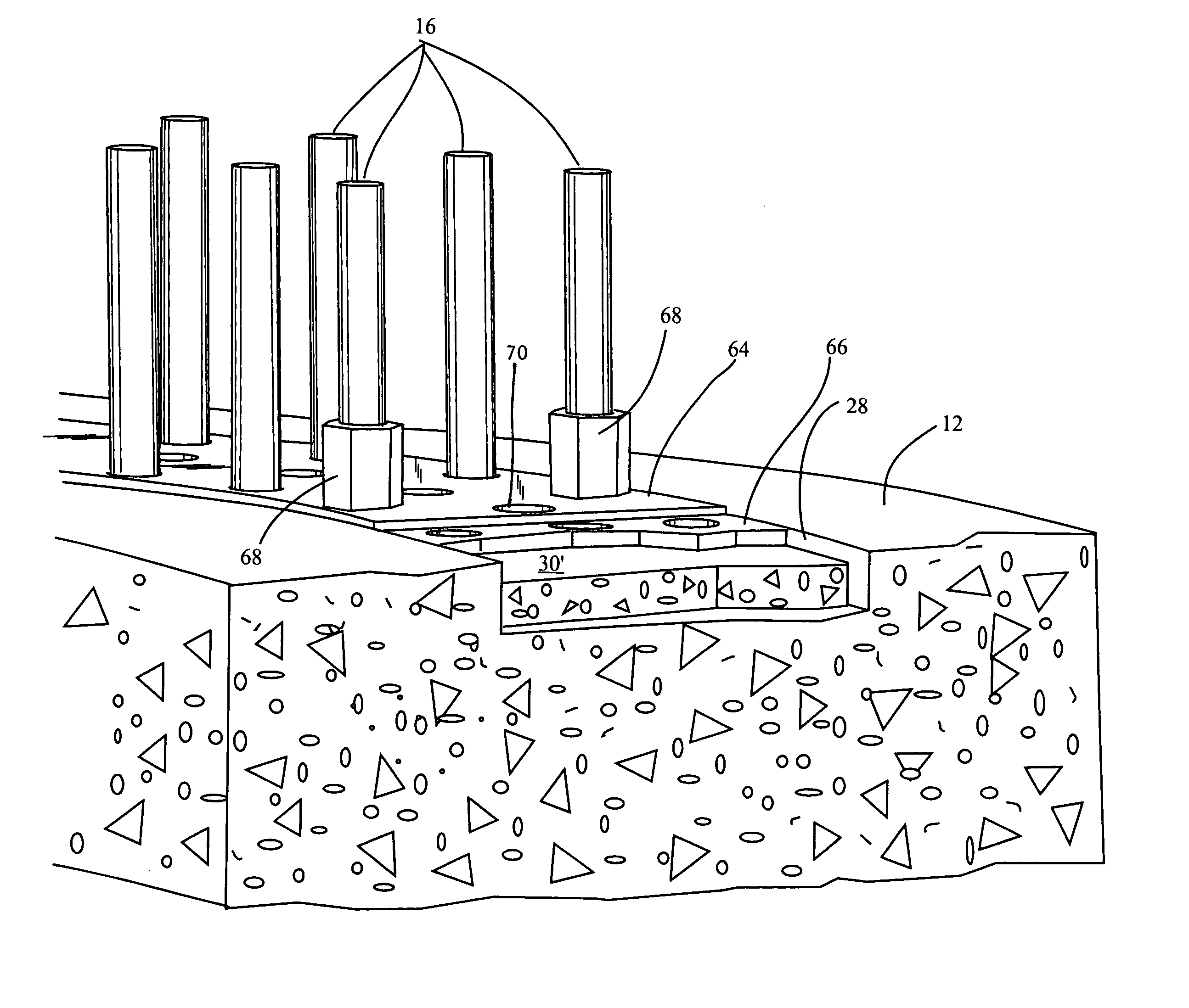
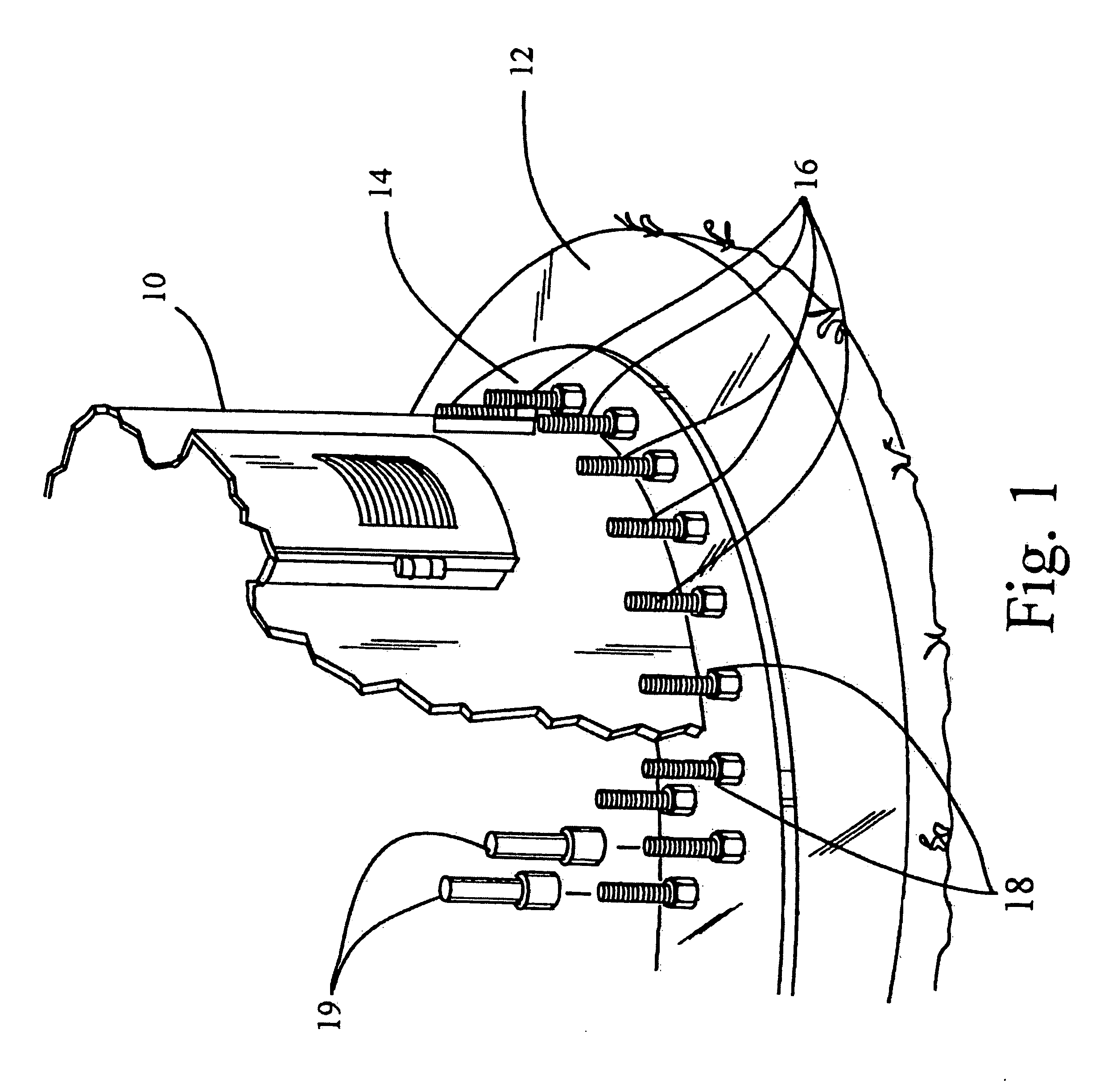
[0036]FIG. 1 generally depicts the base 10 of a wind turbine set upon a foundation 12. Base 10 comprises a flange 14, by which the base is attached to foundation 12 with anchor bolts 16. As shown in FIG. 1, the anchor bolts 16 may be placed in side-by-side pairs, the pairs extending radially from the center of the foundation 12 forming an inner ring of bolts and an outer ring of bolts. The bolt pattern is, of course, determined by the bolt pattern on the mounting flange 14. Each anchor bolt 16 has a corresponding nut 18 which is used to secure the base 10, and to apply tension to the bolt. The exposed portion of each bolt 16 is usually protected with a bolt cap 19.

[0037]A large number of anchor bolts 16 is typically used for this type of foundation. For example, Henderson discloses an embodiment having forty-eight tensioning bolts in the inner ring and forty-eight tensioning bolts in the outer ring for a total of ninety-six. In Henderson's foundation...


PUM


Abstract

An apparatus for use in providing a level grout surface for placement of a wind turbine tower flange, the apparatus comprising a template member levelly suspended on the anchor bolts above the grout trough, wherein the template member comprises a surface to which grout will not adhere. The template member can comprise an upper layer and a lower grout engagement layer, wherein the grout engagement layer comprises a surface to which grout will not adhere. The upper layer can comprise a metallic layer, and the lower layer can comprise a plastic layer, wherein the upper layer and the lower layer are bonded together. The lower layer can comprise polypropylene. The means of bonding are selected from the group consisting of mechanical bonding, thermal bonding and chemical bonding. The grout can comprise an epoxy grout. The template member can be suspended through the use of magnetic nuts or the use of a rotating sleeve. The template member can comprise a plurality of sections, and can comprise a circular form.

Description

CROSS-REFERENCE TO RELATED APPLICATIONS[0001]This is a continuation-in-part of U.S. application Ser. No. 12 / 012,137 filed on Jan. 30, 2008, which application claimed priority to U.S. Provision Application 60 / 898,452 filed on Jan. 30, 2007 and U.S. Provisional Application No. 60 / 905,399 filed on Mar. 5, 2007, for which applications this inventor claims domestic priority.BACKGROUND OF THE INVENTION[0002]This invention generally relates to wind turbines, and anchoring devices, such as bolts, which are used in the foundations of wind turbines because of the high overturning moments to which wind turbines are subjected. The invention more specifically relates to a plastic bolt sleeve used in combination with a threaded anchor, where the plastic sleeve is plastically deformed or “crimped” onto a portion of the threads of the bolt. The invention further discloses methods and devices for crimping the sleeve onto a portion of the bolt threads. Among other benefits, the crimped bolt sleeve pr...

Claims


Application Information

Patent Timeline
Patent Type & Authority Applications(United States)
IPC IPC(8): E02D27/32E04H12/00
CPCE02D27/42Y02E10/728F03D11/045E04H12/085F03D13/22Y02E10/72
Inventor TOOMAN, NORMAN L.
Owner TOOMAN NORMAN L
Why Eureka
Try Eureka