Switching regulator

a switching regulator and regulator technology, applied in the field of switching regulators, can solve the problems of low standby time of the corresponding portable electronic device, long standby time of the portable electronic device, and low switching efficiency of the conventional switching regulator in the light load mode, and achieve the effect of reducing the number of power pulses

Active Publication Date: 2009-02-19
FITIPOWER INTEGRATED TECH INC
View PDF10 Cites 19 Cited by
  • Summary
  • Abstract
  • Description
  • Claims
  • Application Information

AI Technical Summary

Problems solved by technology

If the switching regulators have a high efficiency, particularly in the light load mode, the portable electronic devices may have a long standby time.
Conventional switching regulators have a very low switching efficiency in the light load mode, therefore, the standby time of the corresponding portable electronic devices is low.

Method used


Image

  • Switching regulator
  • Switching regulator

Examples


Embodiment Construction

[0014]Reference will now be made to the drawing to describe, in detail, at least one preferred embodiment of the present switching regulator.

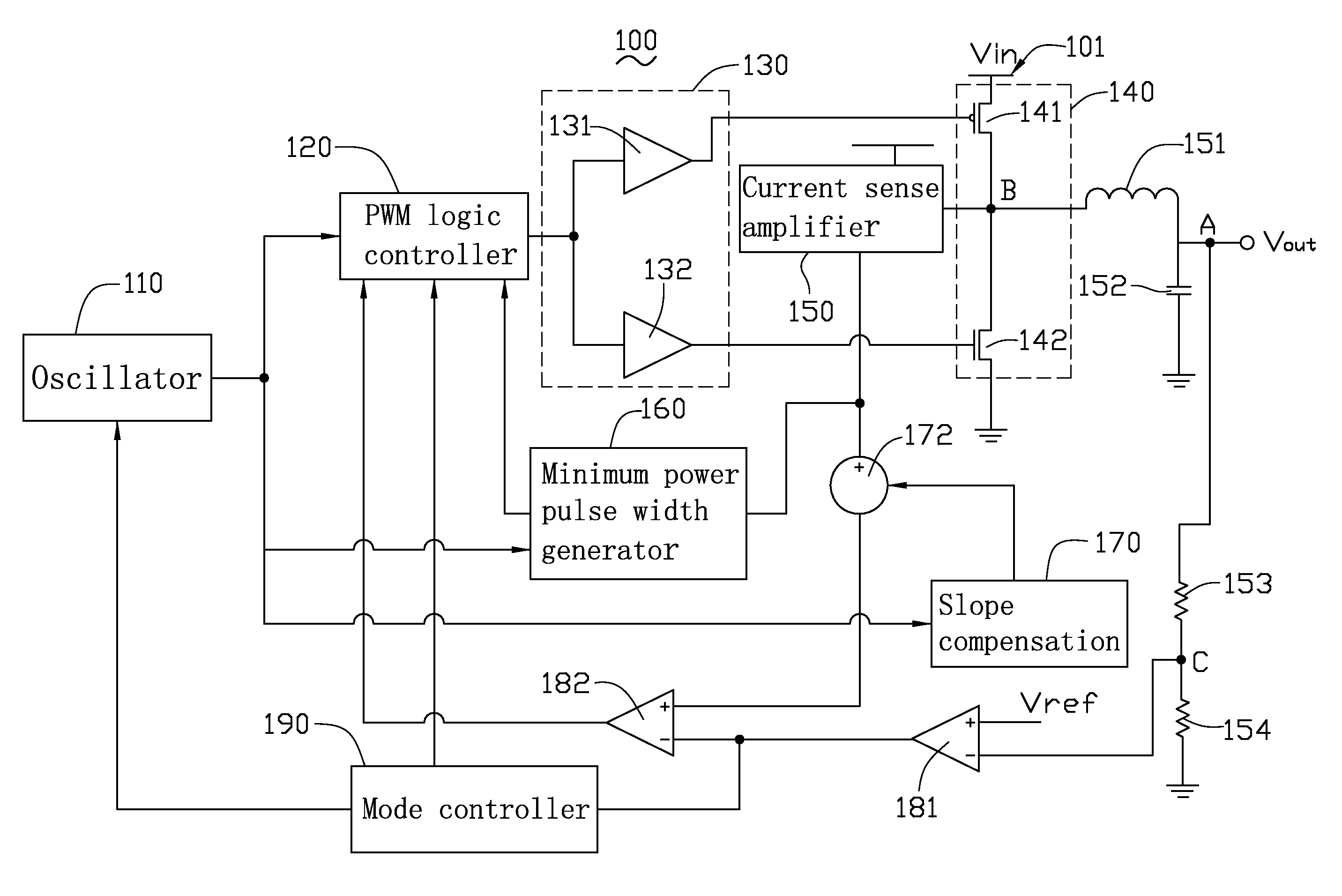
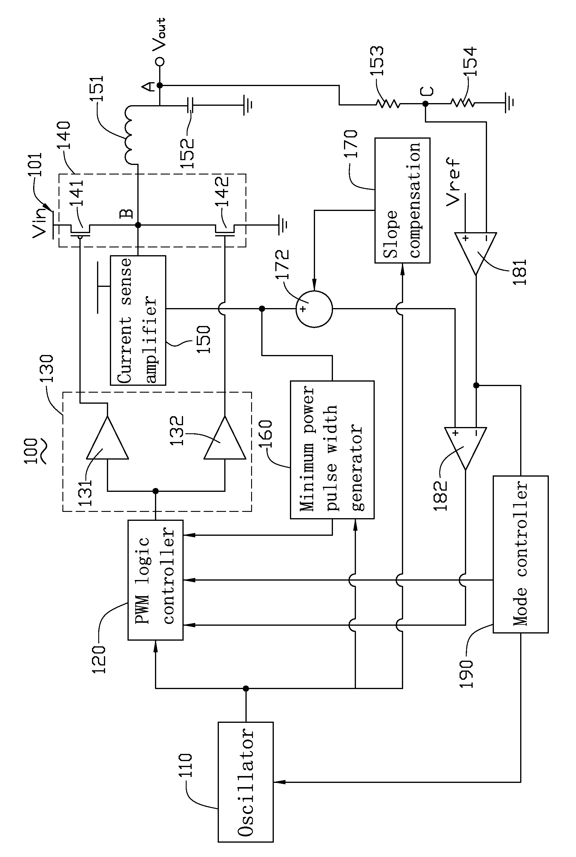
[0015]Referring to the drawing, a switching regulator 100, in accordance with a present embodiment, is provided. The switching regulator 100 includes an oscillator 110, a PWM (pulse-width-modulating) logic controller 120, a driver 130, a switch 140, a current sense amplifier 150, a minimum power pulse width generator 160, an inductor 151 and a capacitor 152.

[0016]The oscillator 110 is configured for generating a square wave having a constant frequency. The PWM logic controller 120 is configured for generating a control voltage. In this exemplary embodiment, the oscillator 110 has an output terminal and an input terminal. The PWM logic controller 120 has a first input terminal, a second input terminal, a third input terminal, a fourth input terminal, and an output terminal. The output terminal of the PWM logic controller 120 is configured for ou...


PUM


Abstract

An exemplary switching regulator, is provided. The switching regulator includes an oscillator, a PWM logic controller, an inductor, a capacitor, a switch, a driver, a current sense amplifier, and a minimum power pulse width generator. The current sense amplifier and the minimum power pulse width generator compose a first feedback loop for generating a first feedback signal to the PWM logic controller.

Description

CROSS-REFERENCE TO RELATED APPLICATIONS[0001]This application claims all benefits accruing under 35 U.S.C. §119 from China Patent Application No. 200710143971.1, filed on Aug. 16, 2007 in the China Intellectual Property Office, the disclosure of which is incorporated herein by reference.BACKGROUND[0002]1. Technical Field[0003]The present invention generally relates to regulators and, particularly, to a switching regulator.[0004]2. Description of Related Art[0005]With the rapid developments of science and technology, portable electronic devices, such as notebook computer, personal digital assistant (PDA), mobile phone, global positioning system (GPS) and multimedia player, are ubiquitous.[0006]One highly desirable feature of these portable electronic devices is a lengthy standby time. The standby time directly relates to the performance measurements of the portable electronic devices. The standby time of portable electronic devices is determined, to some degree, by the efficiency of ...

Claims


Application Information

Patent Timeline
Patent Type & Authority Applications(United States)
IPC IPC(8): G05F1/00
CPCY02B70/1466H02M3/1588Y02B70/10
Inventor FENG, WEI-WENLEE, WEN-YEN
Owner FITIPOWER INTEGRATED TECH INC
Why Eureka
Try Eureka