Wide Exit/Entrance Electronic Article Surveillance Antenna System

an electronic article and antenna system technology, applied in loop antennas with ferromagnetic cores, burglar alarm mechanical actuation, instruments, etc., can solve the problems of system installation, system installation, and failure to detect the presence of false alarms, so as to avoid false alarms and distraction of workers

Inactive Publication Date: 2009-02-19
SENSORMATIC ELECTRONICS CORP
View PDF3 Cites 13 Cited by
  • Summary
  • Abstract
  • Description
  • Claims
  • Application Information

AI Technical Summary

Benefits of technology

[0023]According to another aspect of the present disclosure there is provided an electronic article surveillance antenna system configured to a wide interrogation zones. The system has a number of core transceiver antennas with each connectable to a transmitter. The core transceiver antennas are adapted to be installed adjacent a ceiling of the wide interrogation zone and generate an interrogation signal into the wide interrogation zone. The core transceiver antennas each are connectable to a receiver that receives and detects a response signal from an electronic surveillance marker disposed in the wide interrogation zone. The system also has transceiver antenna coils with each connectable to the transmitter and that are installed adjacent a floor of the wide interrogation zone. The transceiver antenna coils generate the interrogation signal into the wide interrogation zone and each is connected to the receiver to receive and detect the response signal from the electronic surveillance marker disposed in the wide interrogation zone.

Problems solved by technology

Such false alarming distracts workers.
It has been observed that when conventional EAS antenna systems, typically formed of loop antennas, are used in openings wider than about two meters, detection performance begins to deteriorate making exits greater than two meters.
However, this is disfavored because of the expensive construction costs associated with such an installation in the floor and / or ceiling.
Adding loop antennas in existing flooring causes many problems, as the floor must be torn up in order to install the loop antenna, then replaced.
Additionally, such EAS systems often have to be permanently installed into the store.
If installation requires a retrofit into the existing space, often the store's normal operation may be disturbed during installation, i.e., the floor or ceiling will have to be opened for installation of the EAS system then fixed and restored.
Thereafter, if a modification of the entrance or exit occurs, any alteration of the orientation or location of the EAS system is desired (such as if an exit becomes wider), a major amount of work may be required.

Method used


Image

  • Wide Exit/Entrance Electronic Article Surveillance Antenna System
  • Wide Exit/Entrance Electronic Article Surveillance Antenna System
  • Wide Exit/Entrance Electronic Article Surveillance Antenna System

Examples


Embodiment Construction

[0042]The embodiments of the present disclosure will now be described herein in connection with a number of various embodiments. Those skilled in the art will recognize, however, that the features and advantages of the present disclosure may be implemented in a variety of configurations. It is understood, therefore, that the embodiments described herein are presented by way of illustration and not of limitation.

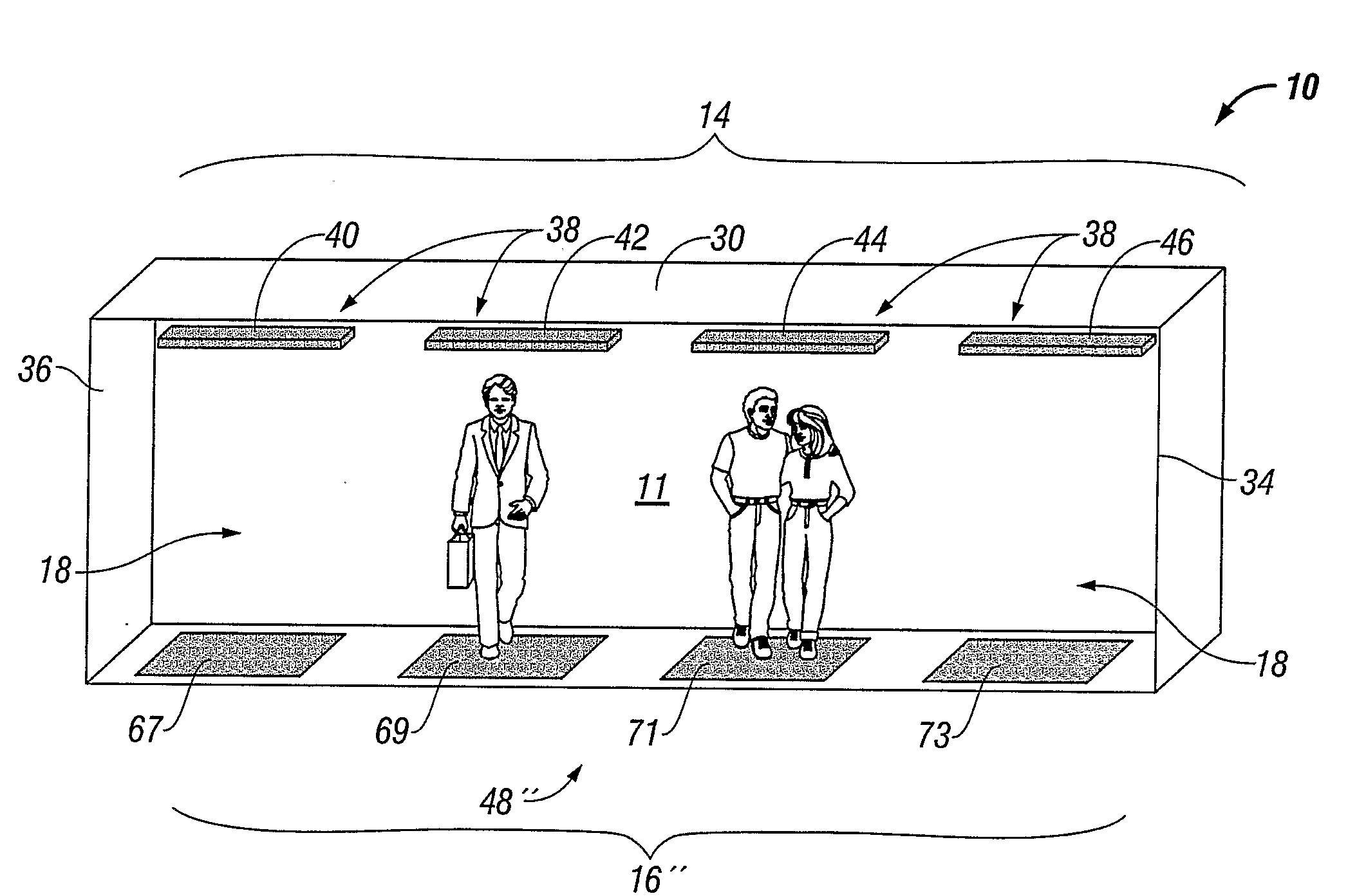
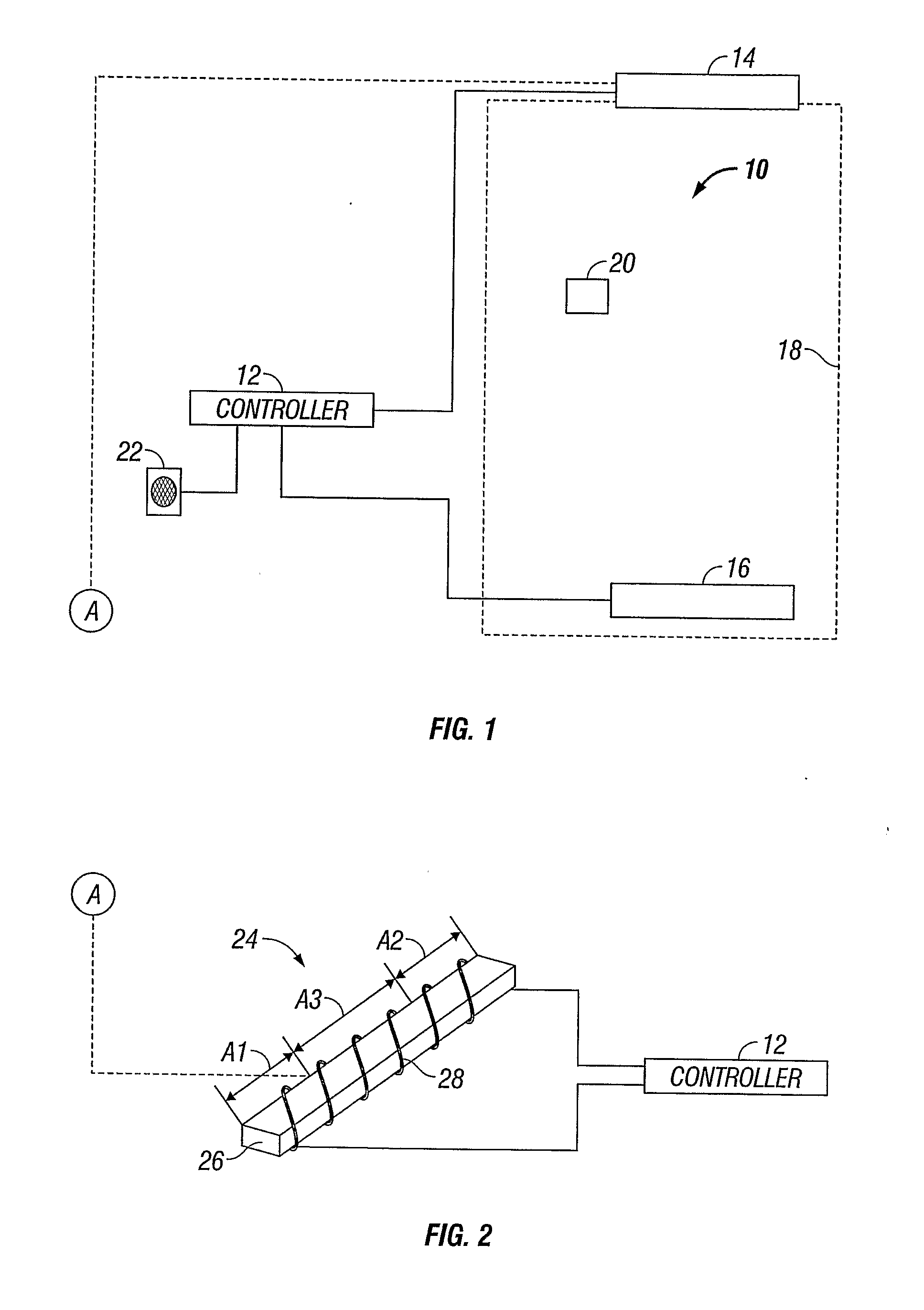
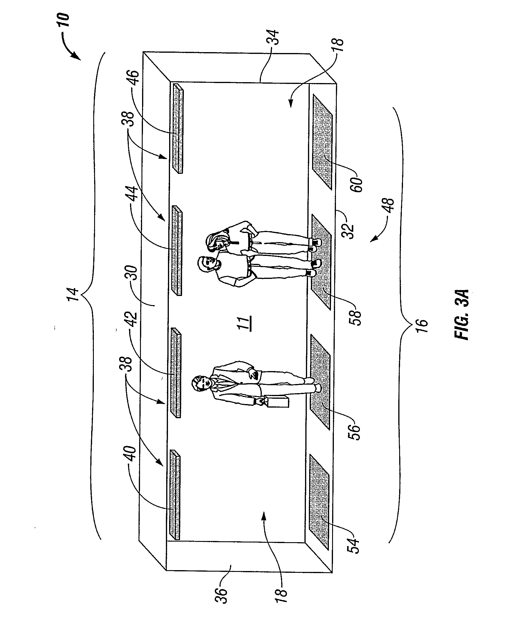
[0043]Referring now to FIG. 1, there is shown a first simplified schematic of an embodiment of the present disclosure. FIG. 1 shows an electronic article surveillance antenna system generally designated as reference numeral 10 for generating a magnetic field to interrogate and detect electronic article surveillance markers.

[0044]The electronic article surveillance antenna system 10 has a controller 12 and a first antenna system 14. The first antenna system 14 is configured as a transceiver and the controller 12 is coupled to the transceiver in a wired manner by connection to ...


PUM


Abstract

An electronic article surveillance antenna system with wide interrogation zones has a number of core transceiver antennas with each connectable to a transmitter. The core transceiver antennas are adapted to be installed adjacent a ceiling of the wide interrogation zone and generate an interrogation signal into the wide interrogation zone. The core transceiver antennas each are connectable to a receiver to receive and detect a response signal from an electronic surveillance marker disposed in the wide interrogation zone. The system also has transceiver antenna coils with each connectable to the transmitter and adapted to be installed adjacent a floor of the wide interrogation zone. The transceiver antenna coils generate the interrogation signal into the wide interrogation zone and each is also connectable to the receiver to receive and detect the response signal from the electronic surveillance marker disposed in the wide interrogation zone.

Description

BACKGROUND[0001]1. Technical Field[0002]The present disclosure relates to an electronic article surveillance (EAS) system. More particularly, the present disclosure relates to an EAS system for exciting an EAS marker in a wide exit / entrance environment.[0003]2. Background of the Related Art[0004]Electronic Article Surveillance (EAS) systems are detection systems that allow the identification of a marker or tag within a given detection region. EAS systems have many uses, but often are used as a security system. Such a security system is for preventing shoplifting, robbery and theft in stores or the removal of property in office buildings; however such systems have been extended to other areas. Such areas include monitoring consumer habits and inventory control. EAS systems come in many different forms and make use of a number of different technologies.[0005]An EAS system includes an electronic detection unit, markers and / or tags, and a detacher or deactivator. The detection units can...

Claims


Application Information

Patent Timeline
Patent Type & Authority Applications(United States)
IPC IPC(8): G08B13/14
CPCG08B13/2474H01Q1/007H01Q7/06H01Q7/00H01Q1/2208
Inventor HALL, STEWART E.COPELAND, RICHARD L.FARRELL, WILLIAM
Owner SENSORMATIC ELECTRONICS CORP
Why Eureka
Try Eureka