Maintenance apparatus, liquid ejection apparatus and nozzle surface maintenance method

a technology of liquid ejection and maintenance method, which is applied in the direction of printing press, office printing, printing, etc., can solve the problems of reducing the ejection performance, and affecting the ejection performance of the nozzle, so as to prevent scratching or abrasion of the hydrophobic film on the nozzle surface, shorten the ejection period, and increase the viscosity

Active Publication Date: 2009-02-19
FUJIFILM CORP
View PDF5 Cites 27 Cited by
  • Summary
  • Abstract
  • Description
  • Claims
  • Application Information

AI Technical Summary

Benefits of technology

[0013]The present invention has been contrived in view of these circumstances, an object thereof being to provide a maintenance apparatus, a liquid ejection apparatus, and a nozzle surface maintenance method, whereby maintenance of the liquid ejection surface can be carried out efficiently, in a short space of time, by means of a space-saving composition.

Problems solved by technology

In an inkjet recording apparatus, when ink, dust, or the like which has been scattered during ejection adheres to the nozzle surface of a head, then the ink ejection direction may deflected so that displacement can occur in the ink depositing positions, and a prescribed amount of ink may not be ejected from the nozzles, so that ejection abnormalities may occur.
When the nozzle surface is wiped by means of a blade, in order to remove the adhering material on the nozzle surface, the lyophobic film on the nozzle surface may be damaged, and this degradation of the lyophobic film may cause a decline in the ejection performance.
However, in a method which wets the nozzle surface and then wipes the nozzle surface using a blade, generally, the wetting process requires approximately the same amount of processing time as the wiping process, and therefore approximately twice the processing time is required in comparison with a method which carries out a wiping process only.
Furthermore, if it is sought to carry out the wetting process in a short period of time, non-uniformities may occur in the wetting of the nozzle surface, and this is undesirable from the viewpoint of protecting the lyophobic film.
Furthermore, if the invention described in Japanese Patent Application Publication No. 2005-96125 is applied to a full line head, then problems of the following kinds arise.
On the other hand, when the cleaning plate is composed to a length which corresponds to the length of the line head in the lengthwise direction thereof, if it is sought to carry out the maintenance of the whole head in one step, then although this contributes to shortening the processing time, the cleaning plate and the movement mechanism of the cleaning plate become large in size, and consequently, the overall size of the apparatus increases and furthermore, this leads to increase in the overall costs of the apparatus.
Moreover, in the method illustrated in FIGS. 3(a) to 3(f) in Japanese Patent Application Publication No. 2005-96125, there is also a possibility that since the cleaning plate is tilted when the solution present between the nozzle plate and the cleaning plate is moved toward the cleaning plate, the solution spreads out over the cleaning plate, and the interior of the apparatus may be soiled by the solution which has dropped outside the cleaning plate therefrom.
Furthermore, in the method illustrated in FIGS. 4(a) to 4(d) in Japanese Patent Application Publication No. 2005-96125, since the cleaning plate is moved in parallel, then there is a possibility that the nozzle surface can become soiled due to the adhering material, which has been moved into the solution on the cleaning plate, becoming reattached to the nozzle surface.
In other words, in the methods illustrated in FIGS. 3(a) to 3(f) and FIG. 4(a) to 4(d) of the Japanese Patent Application Publication No. 2005-96125, in any case, it is difficult to clean the nozzle surface without soiling the nozzle plate or the interior of the apparatus, or to recover the solution used for cleaning the nozzle plate.

Method used


Image

  • Maintenance apparatus, liquid ejection apparatus and nozzle surface maintenance method
  • Maintenance apparatus, liquid ejection apparatus and nozzle surface maintenance method
  • Maintenance apparatus, liquid ejection apparatus and nozzle surface maintenance method

Examples


first embodiment

Description of Maintenance Unit; First Embodiment

[0150]Next, the maintenance unit 100 according to a first embodiment of the present invention will be described. FIG. 7A is a diagram showing a state during maintenance processing using a maintenance unit 100, as viewed from the side face of the head 50 (the side of one end of the head 50 in the lengthwise direction), and FIG. 7B is a diagram of the state shown in FIG. 7A as viewed from the upper side of the head 50 (the opposite side with respect to the ink ejection direction).

[0151]As shown in FIG. 7A, during the carrying out of maintenance processing of the nozzle surface 50A, the maintenance unit 100 is disposed in a maintenance position which is directly below the head 50 and which opposes the nozzle surface 50A of the head 50, and the maintenance unit 100 is moved through the full length of the head 50 in the lengthwise direction (main scanning direction), in a scanning direction W which following the lengthwise direction of the...

second embodiment

[0220]Next, a second embodiment of the present invention will be described with reference to FIG. 12. FIG. 12 shows an ink storage member 320 relating to the second embodiment.

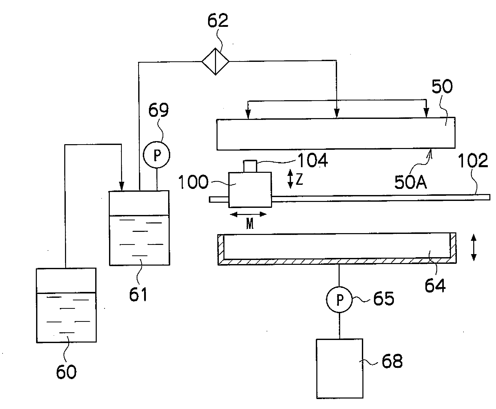
[0221]As shown in FIG. 12, a cleaning liquid supply port 360 which supplies cleaning liquid 322 for wetting the nozzle surface 50A is provided in the approximate central portion of the ink holding surface 321 of the ink storage member 320.

[0222]In other words, the ink storage member 320 comprises a cleaning liquid supply port 360 formed in the approximate central portion of the ink holding surface 321, a cleaning liquid supply channel 362 which is connected to the cleaning liquid supply port 360, a cleaning liquid tank (not illustrated) which stores the cleaning liquid, and a liquid supply apparatus (not illustrated), such as a pump, which sends the cleaning liquid to the cleaning liquid supply port 360.

[0223]In the ink storage member 320 shown in FIG. 12, cleaning liquid 322 is supplied to the ink holding sur...


PUM


Abstract

A maintenance apparatus for a nozzle surface in which a plurality of nozzles ejecting a liquid are formed, in an ejection head having a nozzle row in which the nozzles are aligned in a main scanning direction, has: a liquid storage member which is disposed in a position opposing the nozzle surface of the ejection head at a prescribed distance from the nozzle surface, and which has a liquid holding surface which has a length, in a sub-scanning direction perpendicular to the main scanning direction, corresponding to a length in the sub-scanning direction of a region in which the plurality of nozzles are provided; a liquid supply device which supplies a liquid to the liquid holding surface; a movement device which moves the liquid storage member through a whole length of the nozzle row in the main scanning direction, while bringing the liquid held on the liquid holding surface into contact with the nozzle surface; and a wiping device which wipes the nozzle surface that has been wetted by the liquid supplied to the liquid storage member, while moving subsequently to the liquid storage member, to remove adhering material attached to the nozzle surface.

Description

BACKGROUND OF THE INVENTION[0001]1. Field of the Invention[0002]The present invention relates to a maintenance apparatus, a liquid ejection apparatus and a nozzle surface maintenance method, and more particularly to technology for maintaining the liquid ejection surface of a liquid ejection head.[0003]2. Description of the Related Art[0004]In general, an inkjet recording apparatus which forms a desired image by ejecting ink droplets from a head onto a recording medium is widely used as a generic image forming apparatus. In an inkjet recording apparatus, when ink, dust, or the like which has been scattered during ejection adheres to the nozzle surface of a head, then the ink ejection direction may deflected so that displacement can occur in the ink depositing positions, and a prescribed amount of ink may not be ejected from the nozzles, so that ejection abnormalities may occur. Consequently, an inkjet recording apparatus is composed in such a manner that the adhering material which i...

Claims


Application Information

Patent Timeline
Patent Type & Authority Applications(United States)
IPC IPC(8): B41J2/165
CPCB41J2/16538B41J2/16585B41J2/16552B41J2/16544
Inventor INOUE, HIROSHI
Owner FUJIFILM CORP
Why Eureka
Try Eureka