Maintainable Coplanar Front Face for Silicon Die Array Printhead

a silicon die array and printhead technology, applied in printing, adhesive types, inking apparatus, etc., can solve the problems of affecting the design of die module arrays, and affecting the quality of die modules

Inactive Publication Date: 2009-02-19
XEROX CORP
View PDF6 Cites 65 Cited by
  • Summary
  • Abstract
  • Description
  • Claims
  • Application Information

AI Technical Summary

Problems solved by technology

However, when the separate die modules are cut from a single silicon slab, each die module can be very sharp at the cut edges.
This problem is compounded by the spacing of the individual modules in an array on a printhead unit because of the need to maintain the nozzles during use.
Wiping across sharp cut edges of the individual die modules within an array can damage the wiper blades.
Accordingly, current designs for die module arrays are limited in order to avoid having a wiper structure traverse the sharp edges of the die modules within the array or alone.
However, all of these proposed solutions either negate the effectiveness of the silicon nozzles or add excessive cost to the final device.

Method used


Image

  • Maintainable Coplanar Front Face for Silicon Die Array Printhead
  • Maintainable Coplanar Front Face for Silicon Die Array Printhead
  • Maintainable Coplanar Front Face for Silicon Die Array Printhead

Examples


Embodiment Construction

[0020]Reference will now be made in detail to the exemplary embodiments of the invention, examples of which are illustrated in the accompanying drawings. However, one of ordinary skill in the art would readily recognize that the same principles are equally applicable to, and can be implemented in devices other than ink jet printers, and that any such variations do not depart from the true spirit and scope of the present invention. Moreover, in the following detailed description, references are made to the accompanying figures, which illustrate specific embodiments. Electrical, mechanical, logical and structural changes may be made to the embodiments without departing from the spirit and scope of the present invention. The following detailed description is, therefore, not to be taken in a limiting sense and the scope of the present invention is defined by the appended claims and their equivalents. Wherever possible, the same reference numbers will be used throughout the drawings to r...


PUM

PropertyMeasurementUnit
temperatureaaaaaaaaaa
widthaaaaaaaaaa
areaaaaaaaaaaa

Abstract

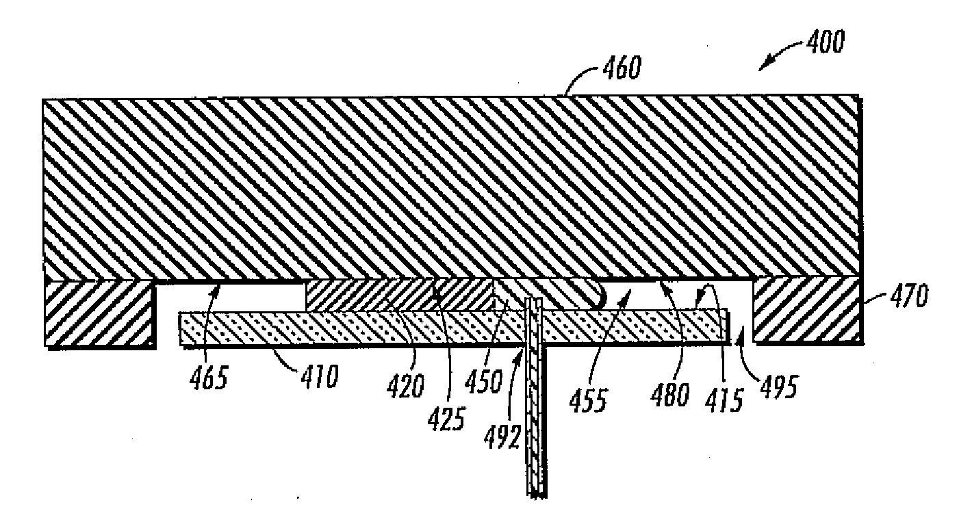
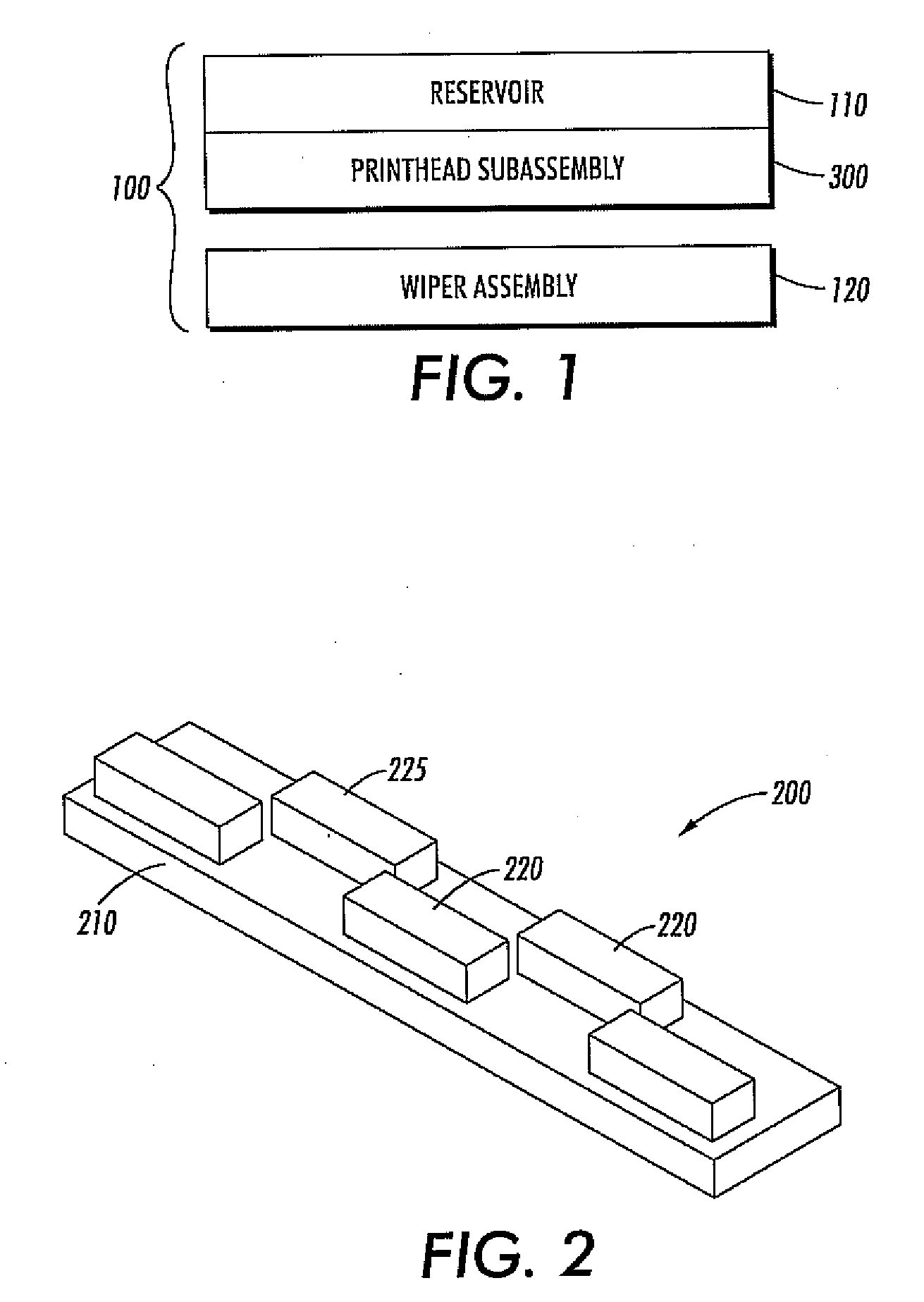
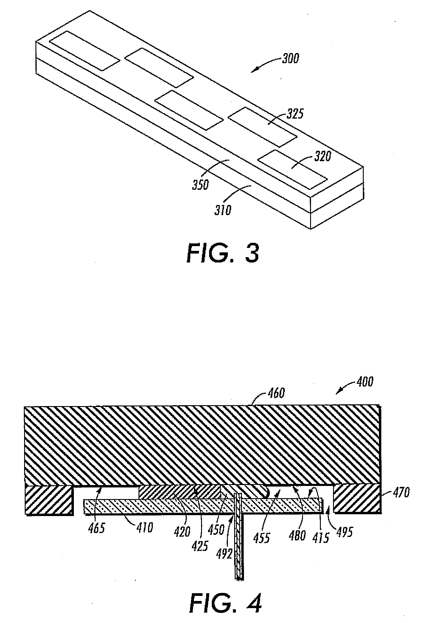
A full width array printhead is provided having a continuous maintainable printhead surface and method of forming the same. The printhead includes a substrate and an array of die modules mounted thereon with a front face of each die module exposed. A hardened fill material surrounds the array of die modules to define a continuous surface coplanar with the front face of the array of die modules.

Description

FIELD OF THE INVENTION[0001]The present invention generally relates to an ink jet printhead, and more particularly, a coplanar surface of a silicon die array printhead.BACKGROUND OF THE INVENTION[0002]In the fabrication of ink jet devices, printhead arrays can be used to increase print speed.[0003]A typical printhead array can include a plurality of subunits known as a die module or chip. Each die module can comprise hundreds or thousands of fluid emitters. An exemplary full-width thermal fluid jet fluid ejecting head has one or more die modules forming a full-width array extending across the full width of the receiving medium on which the image is to be printed. In these fluid ejecting heads with multiple die modules, each die module includes its own ink supply manifold, or multiple die modules can share a common ink supply manifold.[0004]It is known that high quality nozzles can be formed in a silicon die module, malting silicon a preferred material for this purpose. However, when...

Claims


Application Information

Patent Timeline
Patent Type & Authority Applications(United States)
IPC IPC(8): B41J2/14B32B3/14
CPCB41J2/155B41J2202/19Y10T156/1089Y10T29/49885Y10T29/49346B41J2202/20
Inventor NYSTROM, PETER J.GULVIN, PETER M.MEYERS, JOHN P.
Owner XEROX CORP
Why Eureka
Try Eureka