Vehicle Camera System

a camera system and camera technology, applied in the field of vehicle camera systems, can solve the problems of correspondingly long assembling time and longer assembling time, and achieve the effect of facilitating the matching of image sensors and lens assemblies and reducing assembling tim

Active Publication Date: 2009-02-19
HITACHI ASTEMO LTD
View PDF1 Cites 37 Cited by
  • Summary
  • Abstract
  • Description
  • Claims
  • Application Information

AI Technical Summary

Benefits of technology

[0015]According to the present invention, position matching between an image se

Problems solved by technology

The camera structure described in JP-A-2006-33254, however, requires a resin-sealing step during the assembly of the camera, and hence, a correspondingly longer assembling time.
In addition, since the image s

Method used


Image

  • Vehicle Camera System
  • Vehicle Camera System
  • Vehicle Camera System

Examples


Embodiment Construction

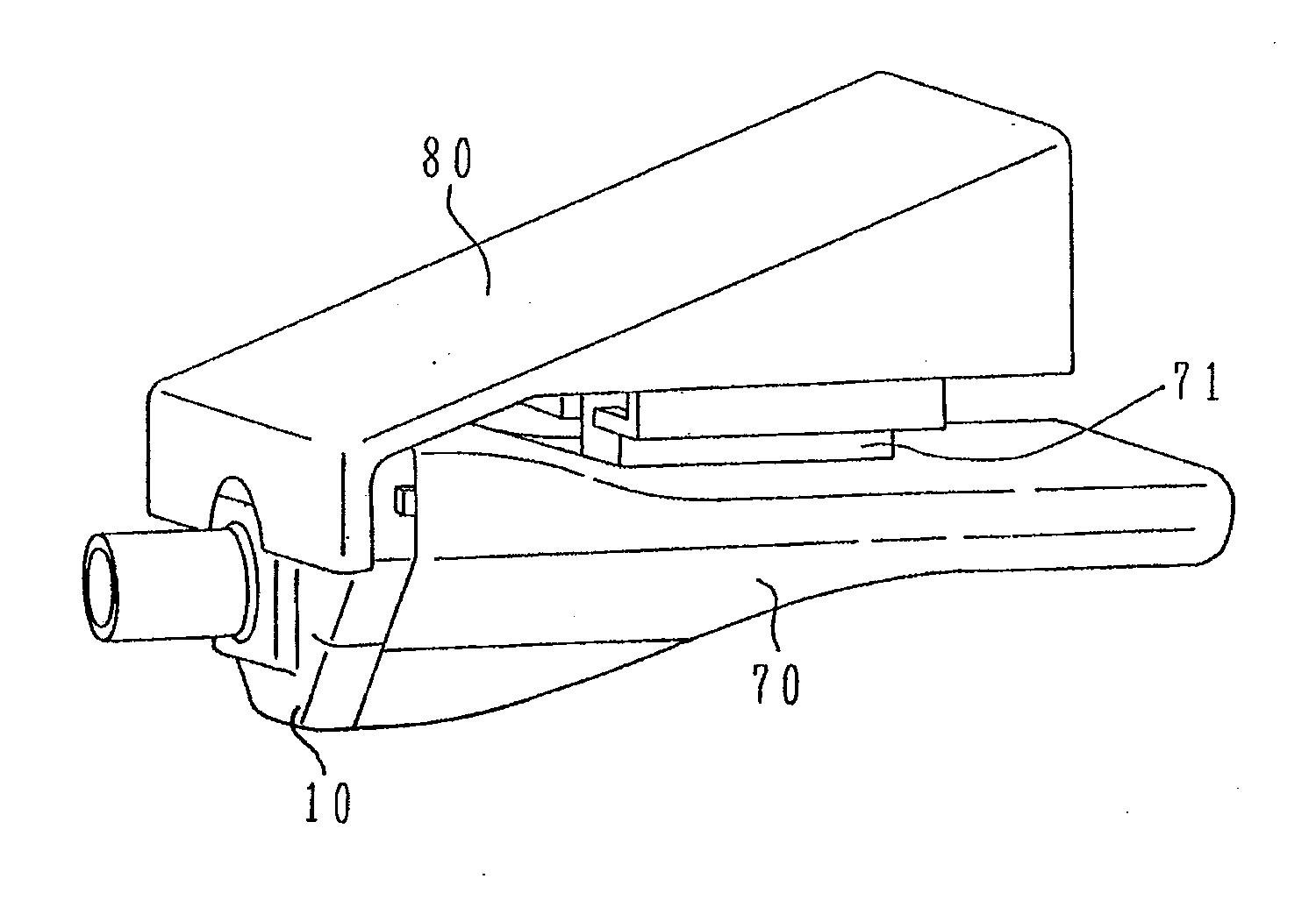
[0031]The configuration of a vehicle camera system according to an embodiment of the present invention will be described using FIGS. 1 to 15. Assembly of the vehicle camera system will also be described.

[0032]The configuration of the vehicle camera system according to the present embodiment is first described using FIG. 1.

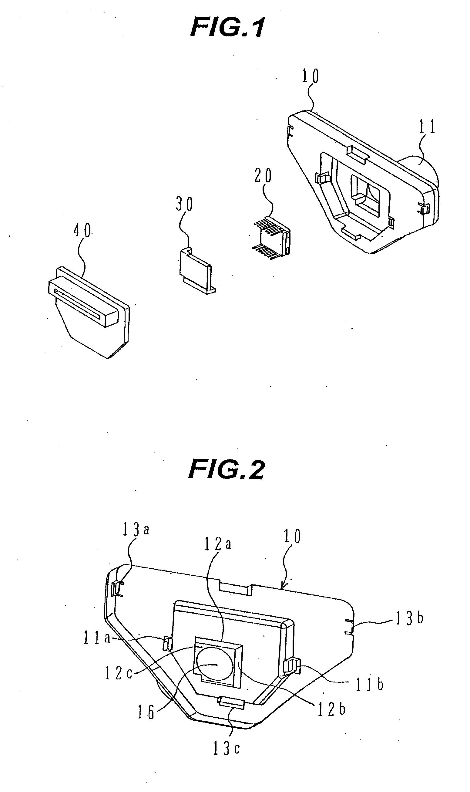
[0033]FIG. 1 is an exploded perspective view showing the configuration of the vehicle camera system according to the present embodiment.

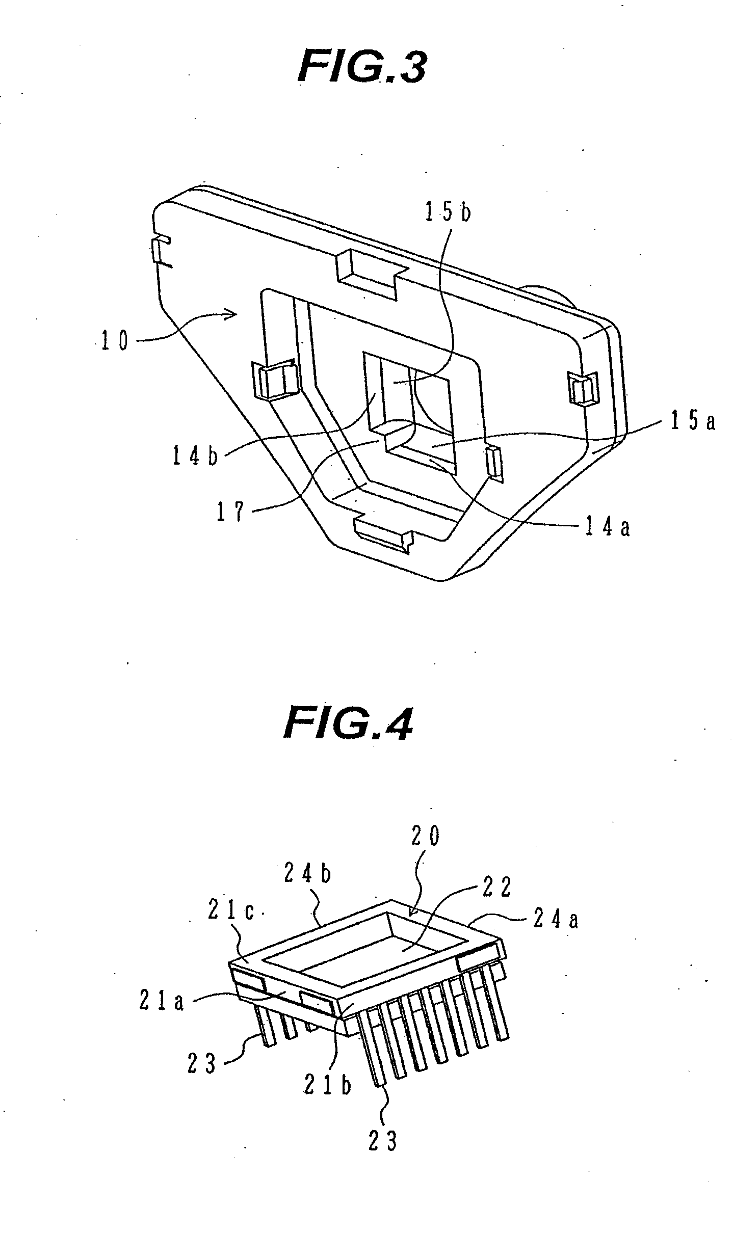
[0034]The vehicle camera system according to the present embodiment includes a lens assembly 10, an image sensor 20, an elastic body 30, and a circuit board 40. Additionally, the lens assembly 10 has a lens barrel 11 including a lens (or lenses)

[0035]The lens barrel 11 contains one or more lenses. Although generally adapted to allow only lens focus to be adjusted independently of the lens assembly 10, the lens barrel 11 can be formed integrally with the lens assembly 10. In this case, a certain degree of defocusing can be absorbed ...


PUM


Abstract

Disclosed herein is a vehicle camera system adapted for easy position matching of an image sensor and a lens assembly, and capable of being reduced in assembling time.
After accommodation of the image sensor 20 in a concave portion 16 of the lens assembly 10, when (a) first and second protrusions 31a, 31b of an elastic body 30 are inserted into first and second clearances 18a, 18b, respectively, and (b) the elastic body 30 is pressed from a direction of a circuit board 40, curved surfaces 15a, 15b convert the pressing direction into a force direction in which first and second datum planes 21a, 21b of the image sensor will be positioned with respect to first and second optical datum planes 12a, 12b, respectively, and the conversion results in first and second opposed planes 24a, 24b of the image sensor being positioned with respect to the first and second optical datum planes 12a, 12b, respectively, and a third datum plane 21c of the image sensor being positioned with respect to a third optical datum plane 12c by the force applied in the pressing direction.

Description

BACKGROUND OF THE INVENTION[0001]1. Field of the Invention[0002]The present invention relates generally to vehicle camera systems that are mounted in automobiles. More particularly, the invention relates to a vehicle camera system improved in assembling efficiency and in assembling accuracy.[0003]2. Description of the Related Art[0004]During the fabrication of a conventional vehicle camera system, there has been a need to adjust and fix the relationship in position between an image sensor and lens assembly of the camera system in order to align the optical axes of these system constituent elements with each other. A large deal of assembling time has therefore been required during the adjustment of the optical axes.[0005]For this reason, in a known camera structure, a resin-sealing portion with a convexity thereon is provided at a marginal portion of an image sensor, and a lens assembly is pressed against a home position on the resin-sealing portion by a two-dimensional elastic body....

Claims


Application Information

Patent Timeline
IPC IPC(8): H04N7/18
CPCH04N5/2254H04N5/2253H04N23/55H04N23/54
Inventor HAYAKAWA, JUNOHSUMI, KEN
Owner HITACHI ASTEMO LTD
Why Eureka
Try Eureka