Optimizations for live event, real-time, 3D object tracking

a technology of live event and object tracking, applied in the field of machine vision systems, can solve the problems of inadequacies of live environment, limited number of places that can be placed on objects, and system experiences a non-uniform resolution per object, etc., and achieves the effect of simple maintenance and operation, and maximum manufacturing and installation costs

Inactive Publication Date: 2009-02-19
MAXX HLDG
View PDF10 Cites 140 Cited by
  • Summary
  • Abstract
  • Description
  • Claims
  • Application Information

AI Technical Summary

Benefits of technology

[0193]8—teach several novel variations using one or more of the present inventors' novel components mixed into the currently available systems.
[0198]4—a system with maximized manufacturing and installation c

Problems solved by technology

Each of these systems shares many drawbacks, especially when considered for use in a live sporting environment such as a sporting contest.
Therefore, the system experiences a non-uniform resolution per object throughout the entire tracking volume.
These techniques are not appropriate for a “live” environment.6—If the tracking energy is IR, then the light sources employed only emit IR without any additional visible light.
As such, they will for instance retroreflect any pre-existing lighting or portable lighting such as camera flashes that are typically used by human observers in a live environment.9—Given that the preferred spherical markers do have an appreciable size, they are limited in the number of places that they can be placed upon the objects, especially in a live environment.
D

Method used


Image

  • Optimizations for live event, real-time, 3D object tracking
  • Optimizations for live event, real-time, 3D object tracking
  • Optimizations for live event, real-time, 3D object tracking

Examples


Embodiment Construction

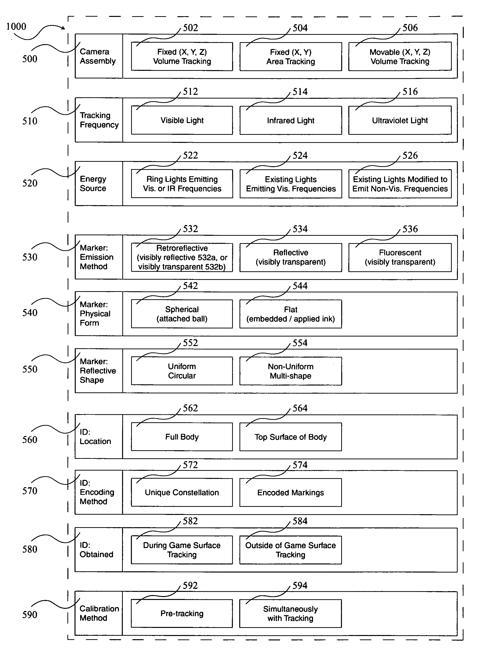
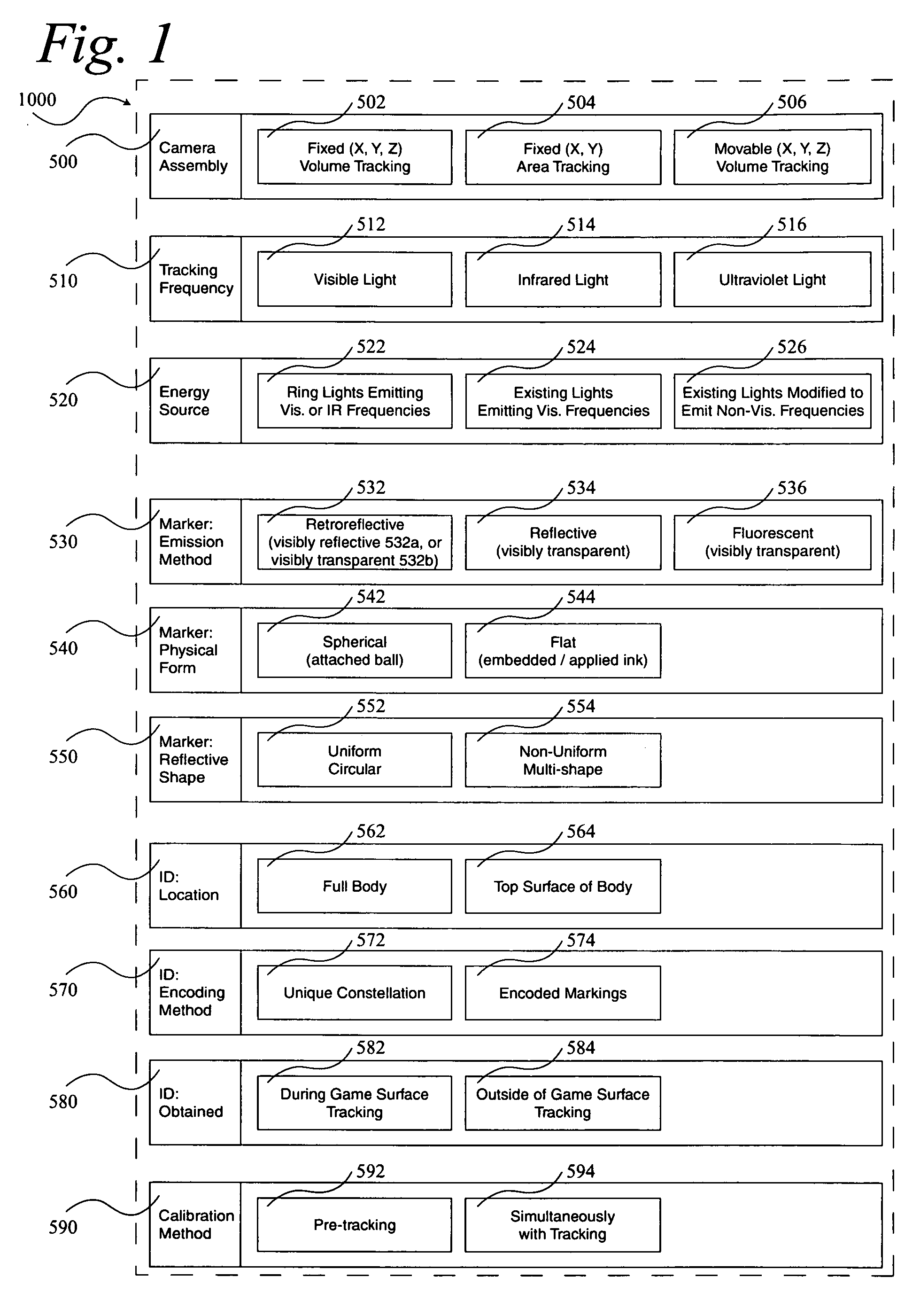
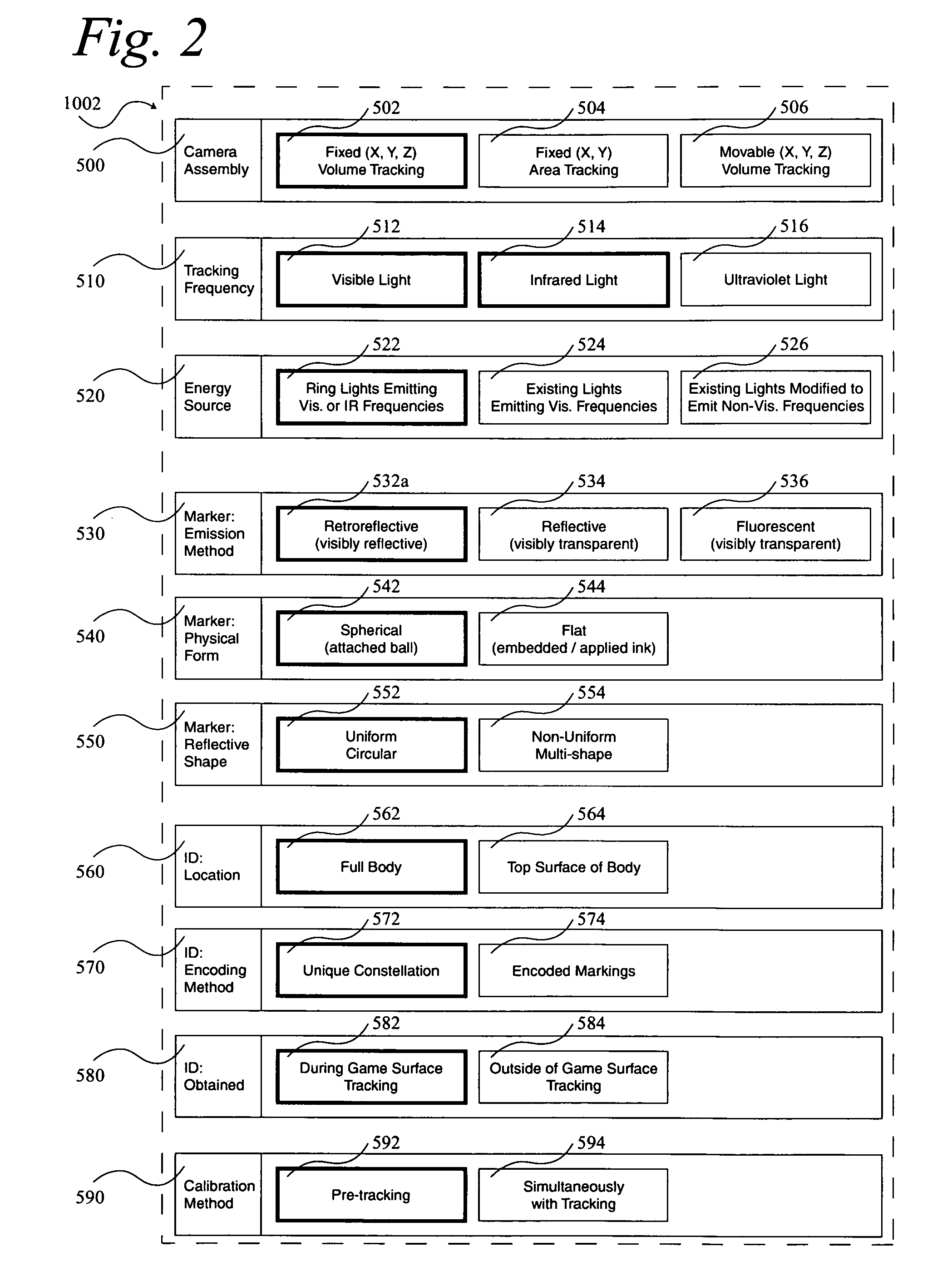
[0240]Referring first to FIG. 1, there is shown a block diagram depicting all of the major components 1000 anticipated to be necessary for the various multi-object tracking machine vision systems according to the present invention. These components are broken into ten groups including Camera Assembly 500, Tracking Frequency 510, Energy Source 520, Marker: Emission Method 530, Marker: Physical Form 540, Marker: Reflective Shape 550, ID: Location 560, ID: Encoding Method 570, ID: Obtained 580 and Calibration Method 590. Camera Assembly 500 can be one or more of Fixed (X, Y, Z) Volume Tracking assemblies 502, Fixed (X, Y) Area Tracking assemblies 504 and Movable (X, Y, Z) Volume Tracking assemblies 506. Tracking Frequency 510 can be one or more of Visible Light 512, Infrared Light 514 or Ultraviolet Light 516. Energy Source 520 can be one or more of Ring Lights Emitting Visible or IR Frequencies 522, Existing Lights Emitting Visible Frequencies 524 and Existing Lights Modified to Emit ...


PUM


Abstract

A system 1000, and its alternates 1002 through 1022, for automatically tracking and videoing the movements of multiple participants and objects during an event. System 1000 and its alternates comprise a scalable area tracking matrix of overhead tracking cameras 120c, whose individual field-of-views 120v combine to form a contiguous view 504m of the performance area where the event is being held. As participants 110, and all other necessary objects such as 103 (e.g. a puck in ice-hockey) and 104 (e.g. a stick in ice-hockey) move about during the event, computer 160 analyzes the images from contiguous view 504m to create a real-time tracking database at least including participant and object centroid locations respective to the performance area, and preferably including their identities matched to these ongoing locations. System 1000 and its alternates then employ the real-time database to automatically direct, without operator intervention, one or more side-view cameras such as 140-a, 140-b, 140-c and 140-d, to maintain optimal viewing of the event. The participants and objects may additionally be marked with encoded or non-encoded, visible or non-visible markers, either denoting centroid locations visible from their upper surfaces, and/or non-centroid locations visible from perspective views. The encoded markers are preferably placed on upper surfaces and detectable by computer 160 as it analyzes the images from contiguous overhead field-of-view 504m, thus providing participant and object identities to correspond with ongoing locations, further enhancing algorithms for subsequently controlling side-view cameras 140-a through 140-d. The non-encoded markers are preferably placed on multiple non-centroid locations at least on the participants that are then adjustably viewable by system 1000 and its alternates as the system uses the determined locations of each participant from the overhead view to automatically adjust one or more side-view cameras to tightly follow the participant. The resulting images from side-view cameras 140-a through 140-d may then be subsequently processed to determine the non-encoded marker locations, thus forming a three dimensional model of each participant and objects movements.

Description

RELATED APPLICATIONS[0001]The present invention is a continuation in part of U.S. patent application Ser. No. 09 / 510,922 filed on Feb. 22, 2000, now issued U.S. Pat. No. 6,707,487 B1, as well as U.S. patent application Ser. No. 09 / 197,219 filed on Nov. 20, 1998, now issued U.S. Pat. No. 6,567,116.TECHNICAL FIELD[0002]The present invention relates to machine vision systems for tracking the movement of multiple objects within a predefined area or volume.BACKGROUND OF THE INVENTION[0003]Several systems currently exist in the commercial marketplace for tracking the movement of one or more objects within a limited area. Such systems are routinely used to follow the movement of human subjects for a range of purposes including medical analysis, input for lifelike animation, as well as sports measurement. The following companies provide machine vision-based motion analysis systems:[0004]Motion Analysis Corporation and their HiRES 3D system;[0005]Vicon with their Vicon 250 and 512 3D motion ...

Claims


Application Information

Patent Timeline
IPC IPC(8): H04N7/18G06T1/00A63B71/06G01S17/66G01S17/87G06T7/20H04N5/232
CPCA63B24/0021G11B27/22A63B2024/0025A63B2208/12A63B2220/13A63B2220/30A63B2220/40A63B2220/806A63B2243/0045G01S17/66G01S17/87G06K9/3216G06K2009/3225G06T7/2033Y10S707/913Y10S707/914Y10S707/915G06K9/00711G11B27/002A63B71/0605A63B2102/24G06T7/246G06V10/245G06V20/40
Inventor AMAN, JAMES A.
Owner MAXX HLDG
Why Eureka
Try Eureka