Multifocal lens with a diffractive optical power region

a multi-focal lens and optical power technology, applied in the field of diffractive optical power, can solve the problems of refractive counterparts, large amounts of chromatic aberration, lens having a diffractive optical power region,

Active Publication Date: 2009-02-19
MITSUI CHEM INC
View PDF102 Cites 64 Cited by
  • Summary
  • Abstract
  • Description
  • Claims
  • Application Information

AI Technical Summary

Benefits of technology

[0021]In an embodiment of the invention, a lens system may include a diffractive optical power region having a first region with a plurality of concentric surface relief diffractive structures for

Problems solved by technology

One of the main disadvantages of using diffractive optical power regions is that they exhibit large amounts of chromatic aberration compared to their refractive counterparts.
As a result of such chromatic aberration, a lens having a diffractive optical power region provides serious vision compromises.
Another disadvantage

Method used


Image

  • Multifocal lens with a diffractive optical power region
  • Multifocal lens with a diffractive optical power region
  • Multifocal lens with a diffractive optical power region

Examples


Embodiment Construction

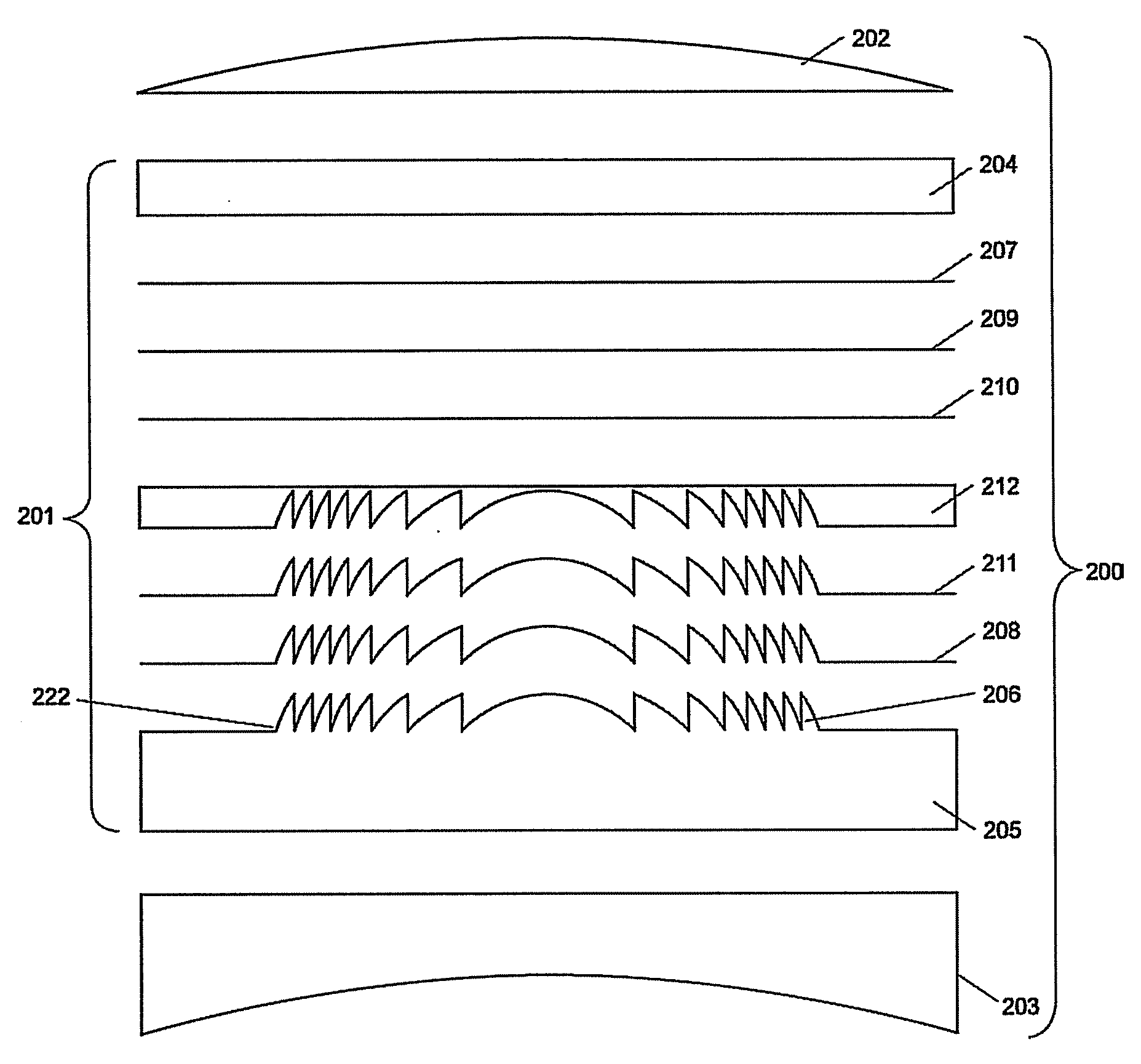
[0059]A diffractive optical power region in a lens may be either static or dynamic. A static diffractive optical power region has an optical power that is fixed at any point. The optical power does not change by the application of electrical or other power. In contrast with a static diffractive optical power region, a dynamic diffractive optical power region has an alterable optical power at one or more positions along the diffractive region. The dynamic diffractive optical power region typically includes a plurality of conducting structures, e.g., pixels or electrode rings, electrically connected to a controller having an electrical power supply. The controller applies electrical power to the conducting structures to create a voltage pattern across the dynamic diffractive optical element, which is predetermined to diffract light to cause the desired optical power.

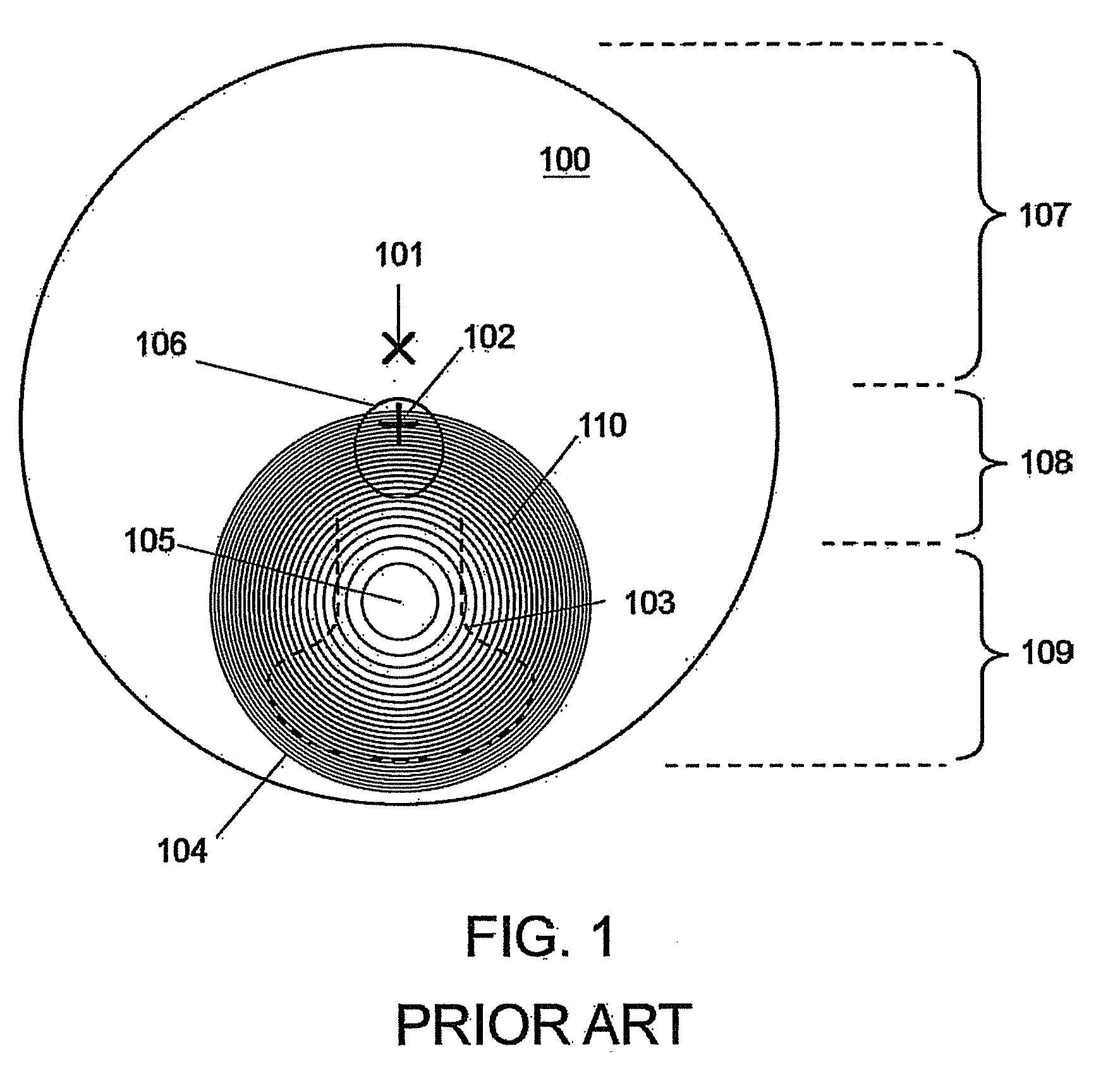
[0060]FIG. 1 shows a front view of a lens 100 having a refractive progressive addition region 103 and a diffractive opti...


PUM


Abstract

A lens system is presented having a diffractive optical power region. The diffractive optical power region has a plurality of concentric surface relief diffractive structures. A greater portion of light incident on a diffractive structure near the center point contributes to the optical power than light incident on a diffractive structure peripherally spaced therefrom.

Description

CROSS REFERENCE TO RELATED APPLICATIONS[0001]This application claims priority from and incorporates by reference in their entirety the following provisional applications:[0002]U.S. Ser. No. 60 / 929,570 filed on Jul. 3, 2007 and entitled “Blending of Diffraction Efficiency for Enhancing Cosmetics of Ophthalmic Lenses Incorporating Diffractive Optical Elements”;[0003]U.S. Ser. No. 60 / 982,182 filed on Oct. 24, 2007 and entitled “Multifocal Spectacle Lens With Non-Rotationally Symmetric Diffractive Optical Power Region and Method For Making Same”;[0004]U.S. Ser. No. 60 / 987,556 filed on Nov. 13, 2007 and entitled “Non-Rotationally Symmetric Diffractive Optical Elements and Method for Making the Same”;[0005]U.S. Ser. No. 61 / 039,079 filed on Mar. 24, 2008 and entitled “Multi-Focal Opthalmic Lenses With Non-Rotationally Symmetric Diffractive Optical Power Region and Method For Making Same”; and[0006]U.S. Ser. No. 61 / 039,081 filed on Mar. 24, 2008 and entitled “Multi-Focal Opthalmic Lenses Wi...

Claims


Application Information

Patent Timeline
IPC IPC(8): G02B27/44G02F1/29
CPCG02B5/1895G02C7/06G02C2202/20G02C7/083G02C7/061
Inventor HADDOCK, JOSHUA N.KOKONASKI, WILLIAMCLARKE, ROGERMATTISON-SHUPNICK, MARKBLUM, RONALD D.
Owner MITSUI CHEM INC
Why Eureka
Try Eureka