Cleaning-in-place system

a technology of cleaning system and conveying apparatus, applied in the direction of cleaning process and apparatus, work treatment device, liquid processing with progressive mechanical movement, etc., can solve the problems of difficult cleaning, partially solving the problem, and increasing the difficulty of cleaning

Active Publication Date: 2009-02-26
HABASIT AG
View PDF21 Cites 16 Cited by
  • Summary
  • Abstract
  • Description
  • Claims
  • Application Information

AI Technical Summary

Problems solved by technology

But this design is only partially solving the problem since the critical hinge areas are still covered by the sprocket rim to a certain extent, when engaged on the sprocket.
During sprocket engagement these teeth enter into the hinge gap between two links and thus push residual matter into this gap, making it again difficult to clean.
The drive surfaces totally covered by the enclosing drive pocket are another place where residuals are physically squeezed in between thus making cleaning more difficult.

Method used


Image

  • Cleaning-in-place system
  • Cleaning-in-place system
  • Cleaning-in-place system

Examples


Embodiment Construction

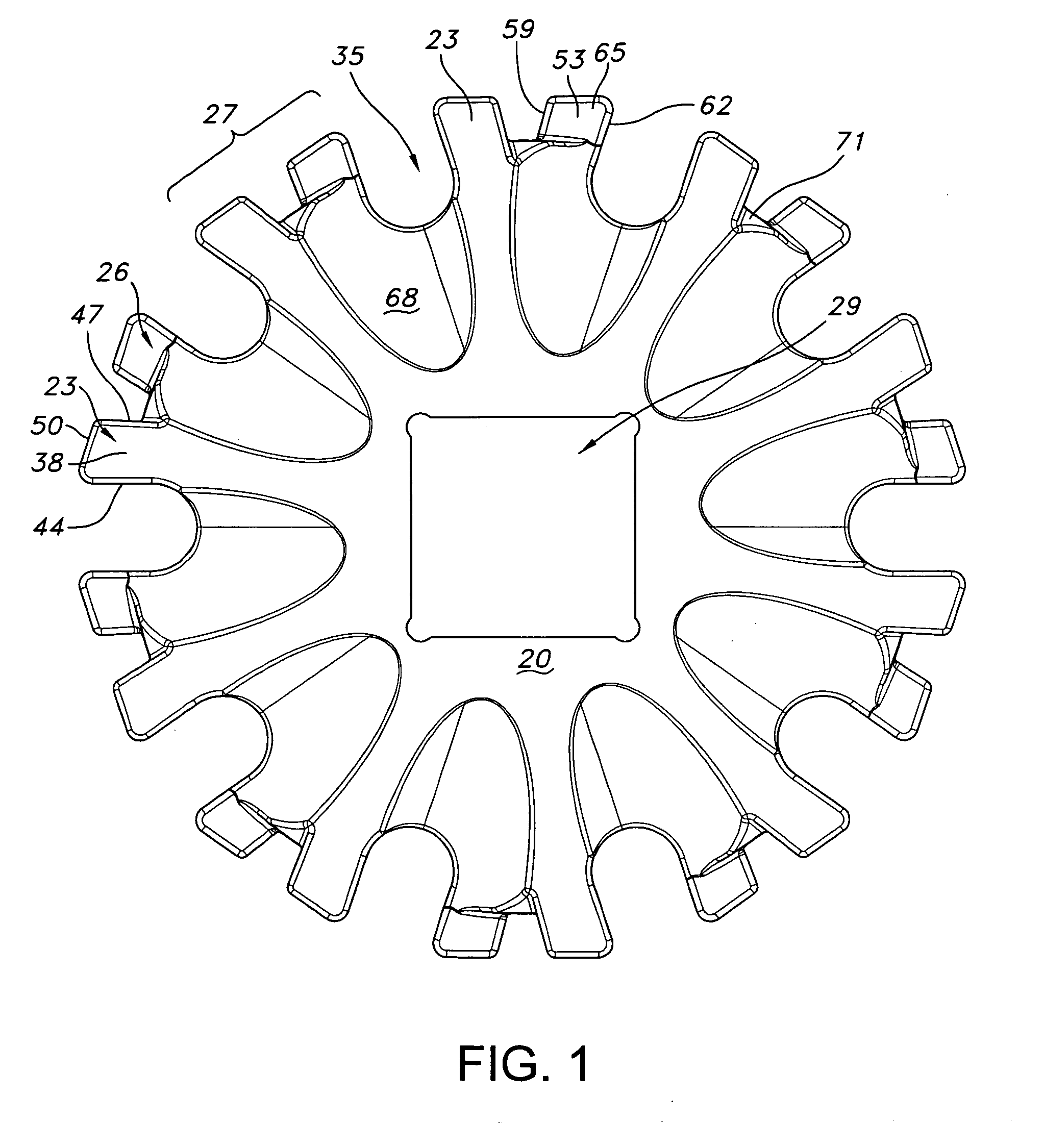
[0033]Referring initially to FIG. 1, a drive sprocket 20 has a plurality of sprocket teeth 23, 26 disposed in pairs 27 around the periphery of the sprocket 20. The sprocket 20 also has a central opening 29 that is formed in the shape of a square. The square shaped opening 29 is sized to receive a square shaft (not shown) for rotating the sprocket 20 to drive a modular belt 32 (FIG. 3). The central opening 29 may be formed in other shapes to accommodate different shaft geometries as will be evident to those of ordinary skill in the art based on this disclosure. A large first opening 35 which may be oval-shaped as shown is formed in the body of the sprocket 20. The first opening 35 is located between adjacent pairs 27 of teeth and is arranged such that it aligns with the hinge area of the modular belt 32 when the belt 32 is engaged with the sprocket 20 as best shown in FIG. 3. As shown the teeth 23 are formed by a pair of side walls 38, 41 (opposite to wall 38); a pair of end walls 44...


PUM

PropertyMeasurementUnit
spray angleaaaaaaaaaa
pressureaaaaaaaaaa
diameteraaaaaaaaaa

Abstract

A cleaning-in-place system for use with an easily cleanable modular belt. The belt has modules with a body having a first opening formed between adjacent pairs of teeth. The opening extends toward the center of the sprocket to provide access to the hinge area, when the belt engages with the sprocket, for application of cleaning fluid.

Description

CROSS-REFERENCE TO RELATED APPLICATION[0001]The present application is a continuation-in-part of U.S. patent application Ser. No. 11 / 672,568 filed on Feb. 8, 2007, which is incorporated herein by reference.FIELD OF THE INVENTION[0002]The present invention relates to modular conveying apparatus.BACKGROUND OF THE INVENTION[0003]Sprockets for driving modular belts are usually made from stainless steel or plastic that is machined or molded. In food processing applications, sprocket drives are a particularly critical area for cleaning. It is important to be able to periodically remove the residual matters totally from the sprockets and on the rear side of the belt, in order to avoid bacteria growth and spoilage of the food processed on the belt. For this purpose sprockets have been designed with large openings to allow cleaning fluid to pass from the side and reach the critical areas to be cleaned.[0004]Such sprockets are disclosed in U.S. Pat. No. Re. 38,607. Typically, the sprocket rim...

Claims


Application Information

Patent Timeline
Patent Type & Authority Applications(United States)
IPC IPC(8): B08B13/00
CPCB08B3/02B08B3/022B65G2207/26B65G45/22B65G23/06
Inventor GULDENFELS, DIETERLUCCHI, MARCO
Owner HABASIT AG
Why Eureka
Try Eureka