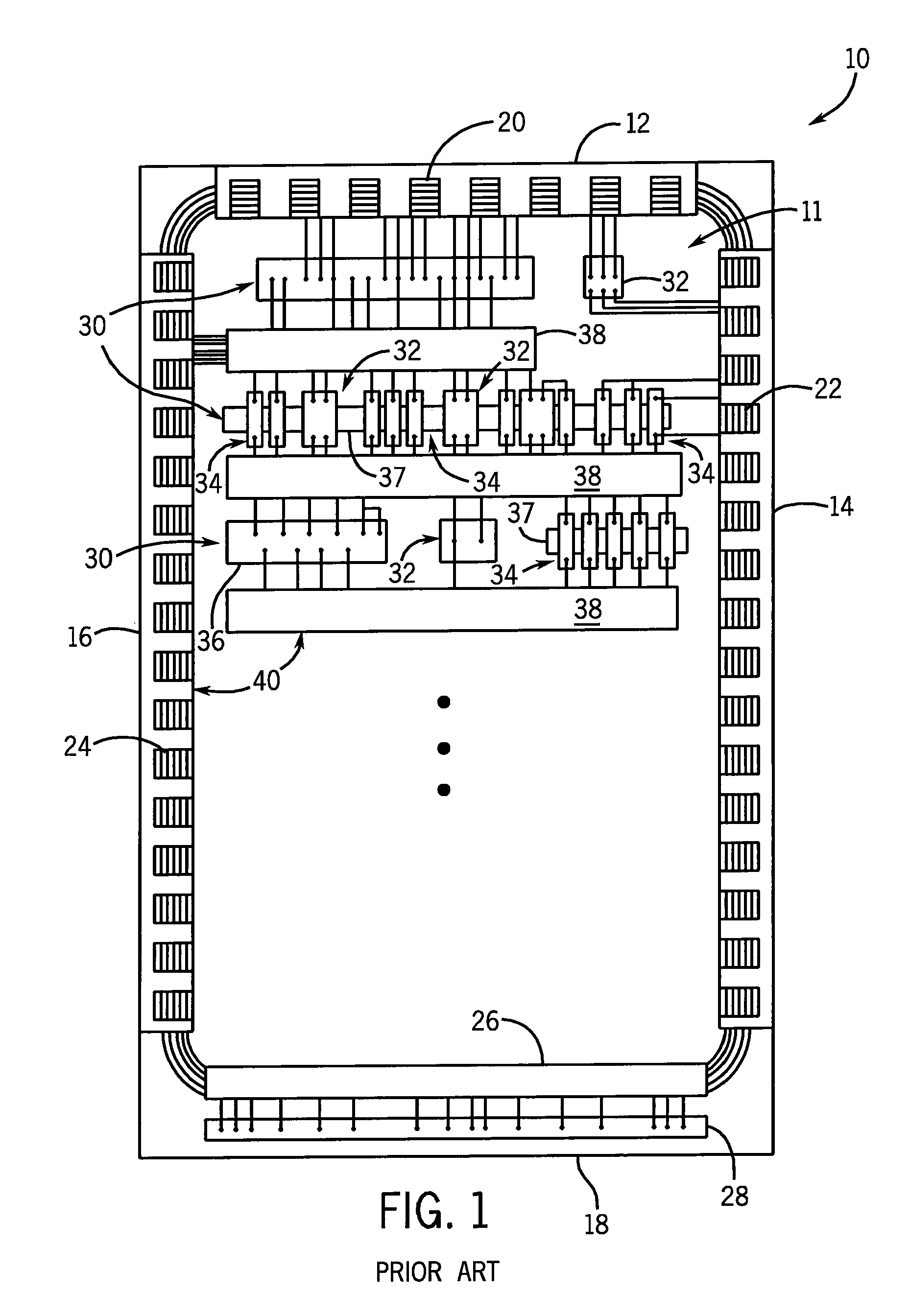
The complexity of wiring these systems is ever increasing as the integration of electrical, electro-mechanical, and digital components 30 become increasingly sophisticated and complex.
However, these designs are generally undesirable due to the increased wiring / manufacturing costs and difficulty accessing or replacing wired components after the manufacturing process.
While such systems can reduce some of the space required to accommodate components mounted on a DIN rail 37, they suffer from numerous drawbacks.
This may create undesirable, if not unsafe, conditions within the panel 10.
However, these systems still require significant space between components located above or below the u-brackets in the panel so that wires passing under the DIN rails can be accessed during wiring or field replacements.
Furthermore, these systems do not provide any wiring conduit within which to confine the wires running under the u-bracket.
As such, tie-wrapped wire bundles are typically required, which add to wiring / manufacturing costs.
However, these systems place significant stress upon the hinge because the weight of the cover, DIN rail, and all components mounted on the DIN rail is applied to a single hinge.
Accordingly, it is not uncommon for the hinges in these systems to fail after repeated use.
In particular, if the cover and DIN rail are left in the open position for an extended length of time, such as is required during wiring of the panel, the hinge will bend and / or break and require replacement.
This leads to significant cost in materials and labor because the components mounted on the DIN rail must be removed along with the wire passage and cover, and then remounted on a new DIN rail, cover, and wire passage
assembly.
Furthermore, these systems require excessive amounts of slack wire and / or circuitous wiring routes in order to allow the DIN rail to swing through the wide rotational path required to reach the open position without the wires restricting movement of the DIN rail.
However, this design also includes a number of drawbacks.
First, the use of snap-in hinges is undesirable in many applications because they merely rely on frictional forces to secure the DIN rail and associated components.
Accordingly, in a manner similar to the above-described cover-mounted DIN rails, undesirable, if not unsafe, conditions may be created by dangling components.
Additionally, when wiring components to the elevated DIN rail and attempting to
route wires into the wire passage, the wiring process may become particularly arduous.
Furthermore, when mounted on a vertically extending wall or panel, the trapezoidal cover will either snap shut or have a tendency to dislodge from the mounting, depending upon which hinge is opened.

