Method and electrical switching apparatus including a number of accessories employing wireless communication

a technology of wireless communication and electrical switching equipment, applied in the direction of protective switch details, emergency protective arrangements for limiting excess voltage/current, instruments, etc., can solve the problems of the cost and time consumption of wire installation,

Inactive Publication Date: 2009-02-26
EATON CORP
View PDF9 Cites 29 Cited by
  • Summary
  • Abstract
  • Description
  • Claims
  • Application Information

AI Technical Summary

Problems solved by technology

The installation of these wires is costly and time consuming.
The

Method used


Image

  • Method and electrical switching apparatus including a number of accessories employing wireless communication
  • Method and electrical switching apparatus including a number of accessories employing wireless communication
  • Method and electrical switching apparatus including a number of accessories employing wireless communication

Examples


example 1

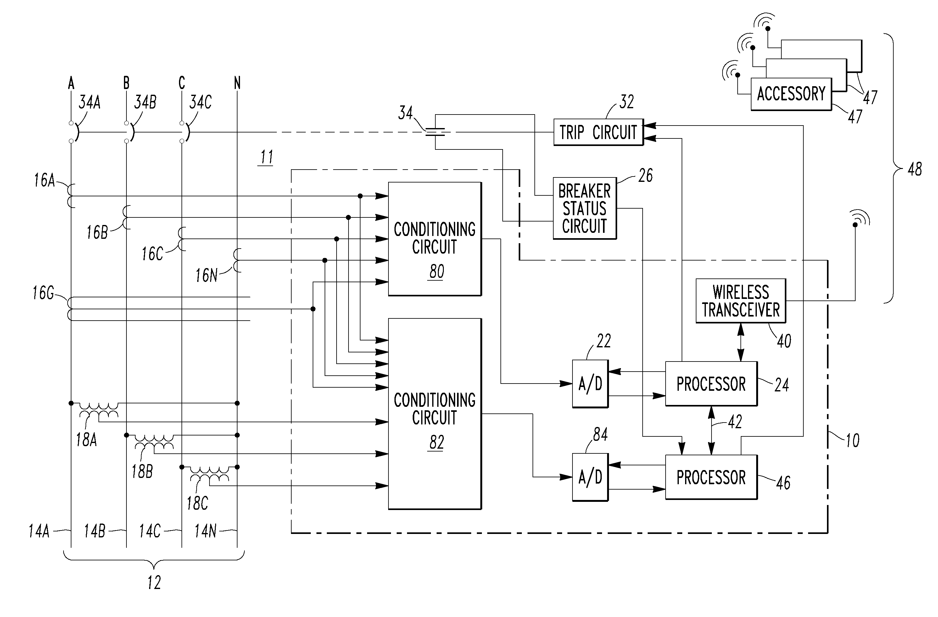
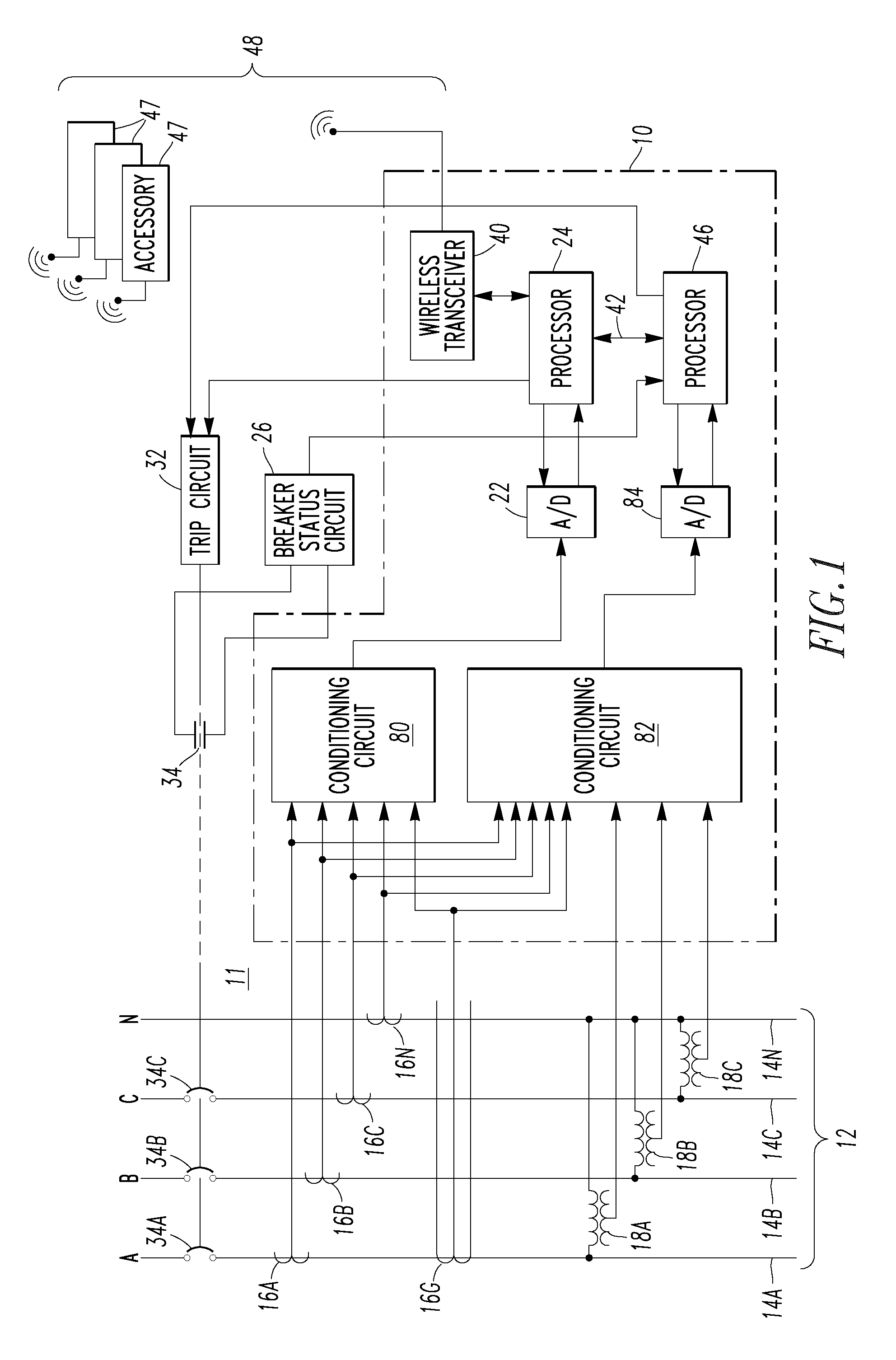
[0033]Referring to FIG. 1, an electronic trip unit 10 of a circuit interrupter, such as circuit breaker 11, protects and captures waveforms in an AC electrical power distribution system 12, which represents a load. The power distribution system 12 (e.g., without limitation, an electrical system; an AC electric power system; a power circuit) has three phase conductors 14A,14B,14C, and a neutral conductor 14N. Current transformers 16A,16B,16C,16N sense current flowing in each of these conductors. Current transformer 16G is a zero sequence transformer, which indirectly measures ground current by directly measuring the sum of the phase and neutral currents. These currents are sensed by conditioning circuits 80 and 82, which prepare the signals for processing by analog-to-digital (A / D) converters 22 and 84, respectively. Phase-to-neutral voltages are sensed from the three phase conductors 14A,14B,14C by respective potential transformers 18A,18B,18C and are inputted to conditioning circui...

example 2

[0038]Referring to FIG. 7, another circuit interrupter, such as circuit breaker 100 is shown. The circuit breaker 100 includes separable contacts 102, an operating mechanism 104 structured to open and close the separable contacts, a first processor (e.g., without limitation, a microprocessor (μP)) 106 cooperating with the operating mechanism 104 to determine an open or closed state 107 of the separable contacts 102, and a number of accessories 108. Each of the accessories 108 includes a wireless receiver (RX) 110, a second processor (e.g., without limitation, a microprocessor (μP)) 112 and a number of outputs 114. The circuit breaker 100 further includes a wireless transmitter (TX) 115 structured to wirelessly transmit the open or closed state of the separable contacts 102 from the first processor 106 to the wireless receiver 110 of the accessories 108. The wireless receiver 110 is structured to wirelessly receive the open or closed state of the separable contacts 102 from the wirel...

example 3

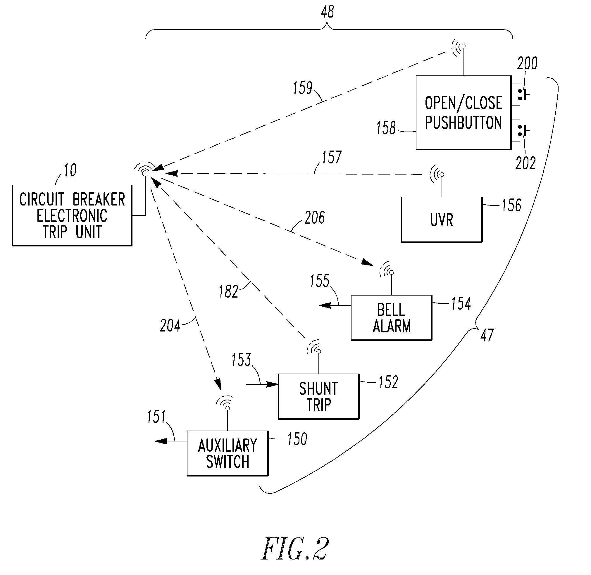
[0039]In this example, the circuit breaker 100 includes a circuit breaker housing 116, and a number of the accessories 108 are located on or internal to (as shown in FIG. 7) the housing 116 as opposed to being remote from a circuit breaker as is shown with the circuit breaker trip unit 10 of FIG. 2.


PUM


Abstract

A circuit breaker includes separable contacts, an operating mechanism opening and closing the contacts, a first processor determining an open or closed state of the contacts, and a wireless transceiver transmitting the open or closed state from the first processor and receiving a signal. A first accessory includes a wireless receiver, a second processor and outputs. A second accessory includes a wireless transmitter, a third processor and a circuit generating the signal for or communicating the signal to the third processor, which outputs the signal to the wireless transmitter, which transmits the signal to the wireless transceiver. The first processor receives the signal from the wireless transceiver and causes the mechanism to open or close the contacts. The wireless receiver receives the open or closed state from the wireless transceiver. The second processor receives the open or closed state from the wireless receiver and outputs the same to the outputs.

Description

BACKGROUND OF THE INVENTION[0001]1. Field of the Invention[0002]This invention pertains generally to electrical switching apparatus and, more particularly, to such apparatus including a number of accessories. The invention also relates to methods of communicating between a number of accessories and an electrical switching apparatus.[0003]2. Background Information[0004]Electrical switching apparatus, such as circuit breakers, are widely used in industrial, commercial and residential applications for protecting electrical conductors and apparatus. Circuit breakers, for example, are used to protect electrical distribution systems from damage due to an overcurrent condition, such as an overload condition or a relatively high level short circuit or fault condition. In small circuit breakers, commonly referred to as miniature circuit breakers, used for residential and light commercial applications, such protection is typically provided by a thermal-magnetic trip device. This trip device i...

Claims


Application Information

Patent Timeline
IPC IPC(8): H02H3/08
CPCH01H9/167H01H2071/0278H01H83/12H01H71/04
Inventor BEATTY, WILLIAM E.DAS, SUJIT R.LAGREE, JAMES L.MORT, DEBORAH K.
Owner EATON CORP
Why Eureka
Try Eureka