
Inkjet recording apparatus

a recording apparatus and inkjet technology, applied in the direction of printing, other printing apparatus, thin material processing, etc., can solve the problems of lowering printing throughput, needing to move the plug, and the suction hole is apart from the plug by a relatively long distance, so as to reduce the suction force , the structure of the image recording apparatus is made simpl

Active Publication Date: 2009-02-26
BROTHER KOGYO KK
View PDF2 Cites 18 Cited by
  • Summary
  • Abstract
  • Description
  • Claims
  • Application Information

AI Technical Summary

Benefits of technology

The present invention provides an image recording apparatus that allows for easy and quick separation of a recording medium from the drum. The apparatus includes a conveyance mechanism, suction unit, supply mechanism, record head, ejection path, and blocker. The blocker is placed inside the apparatus and blocks the inner opening of a suction hole, reducing the suction force and allowing the recording medium to be easily separated from the drum. The blocker does not need to be moved, simplifying the structure of the apparatus. The technical effect of the invention is to improve printing throughput and simplify the structure of the image recording apparatus.

Problems solved by technology

In the structure, however, the suction holes are apart from the plug by a relatively long distance.
This causes difficulty in promptly separating the sheet from the outer circumferential surface, consequently lowering the printing throughput.
Further, the plug needs to be moved, and this requires a complicated structure.

Method used


Image

  • Inkjet recording apparatus
  • Inkjet recording apparatus
  • Inkjet recording apparatus

Examples


embodiment 1

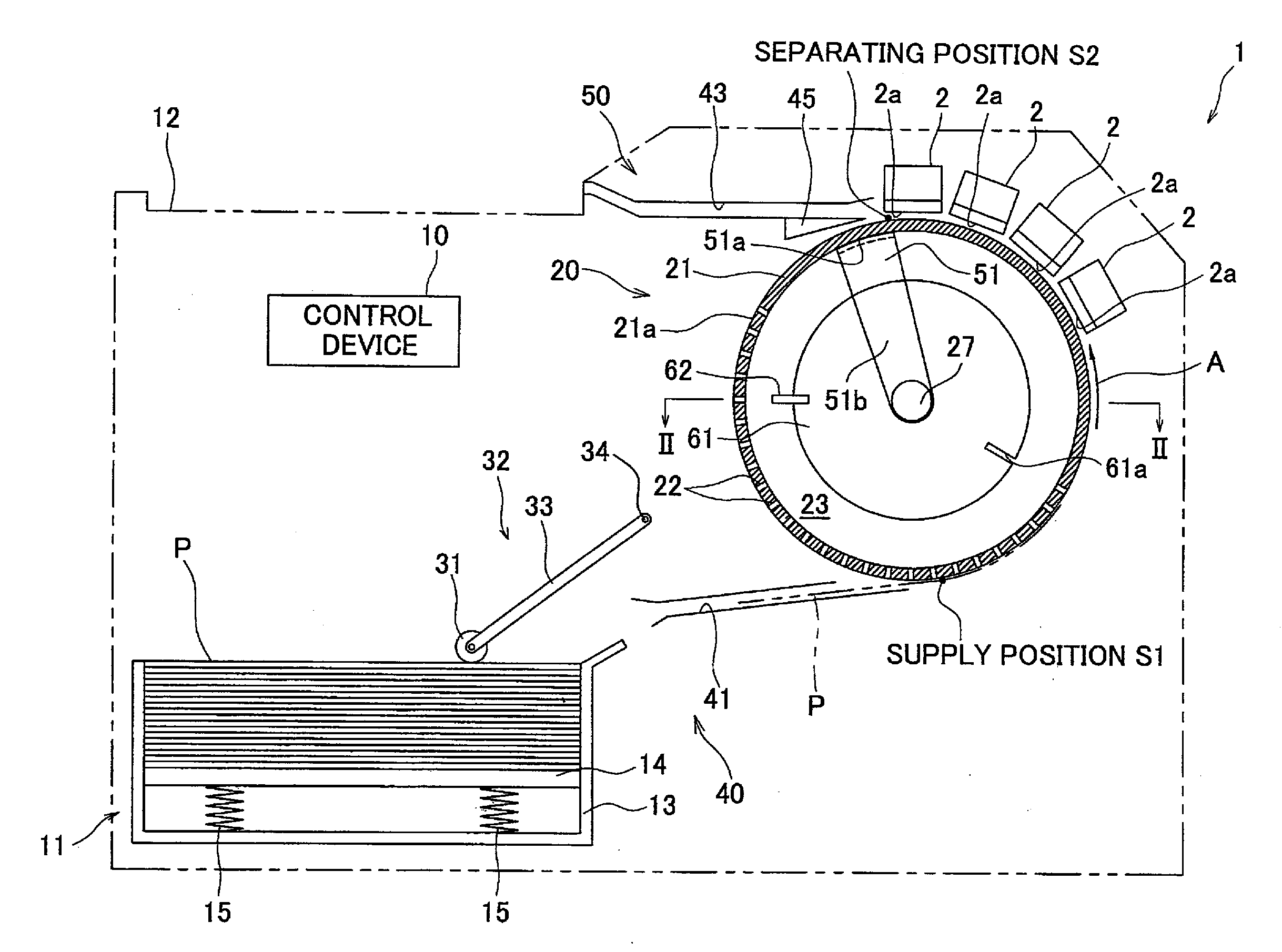
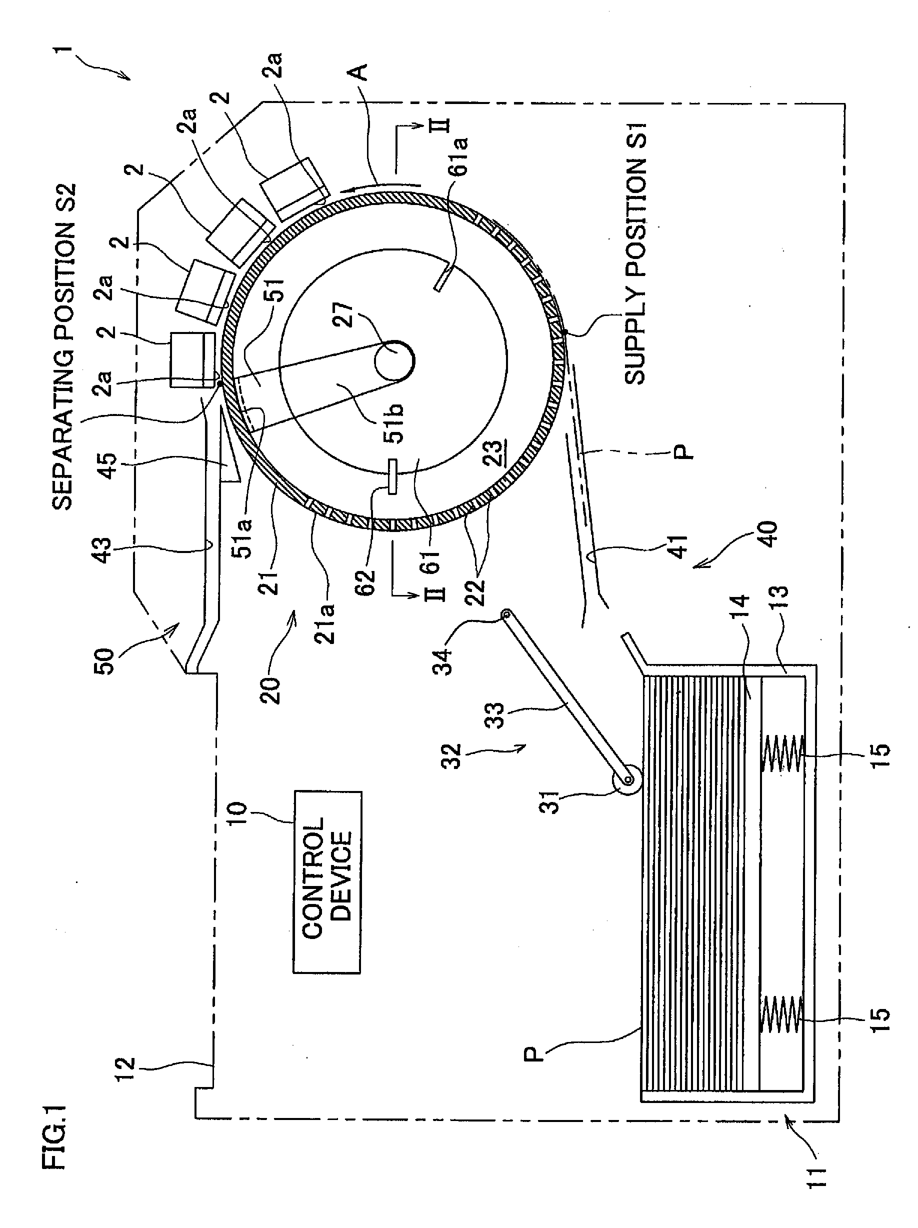
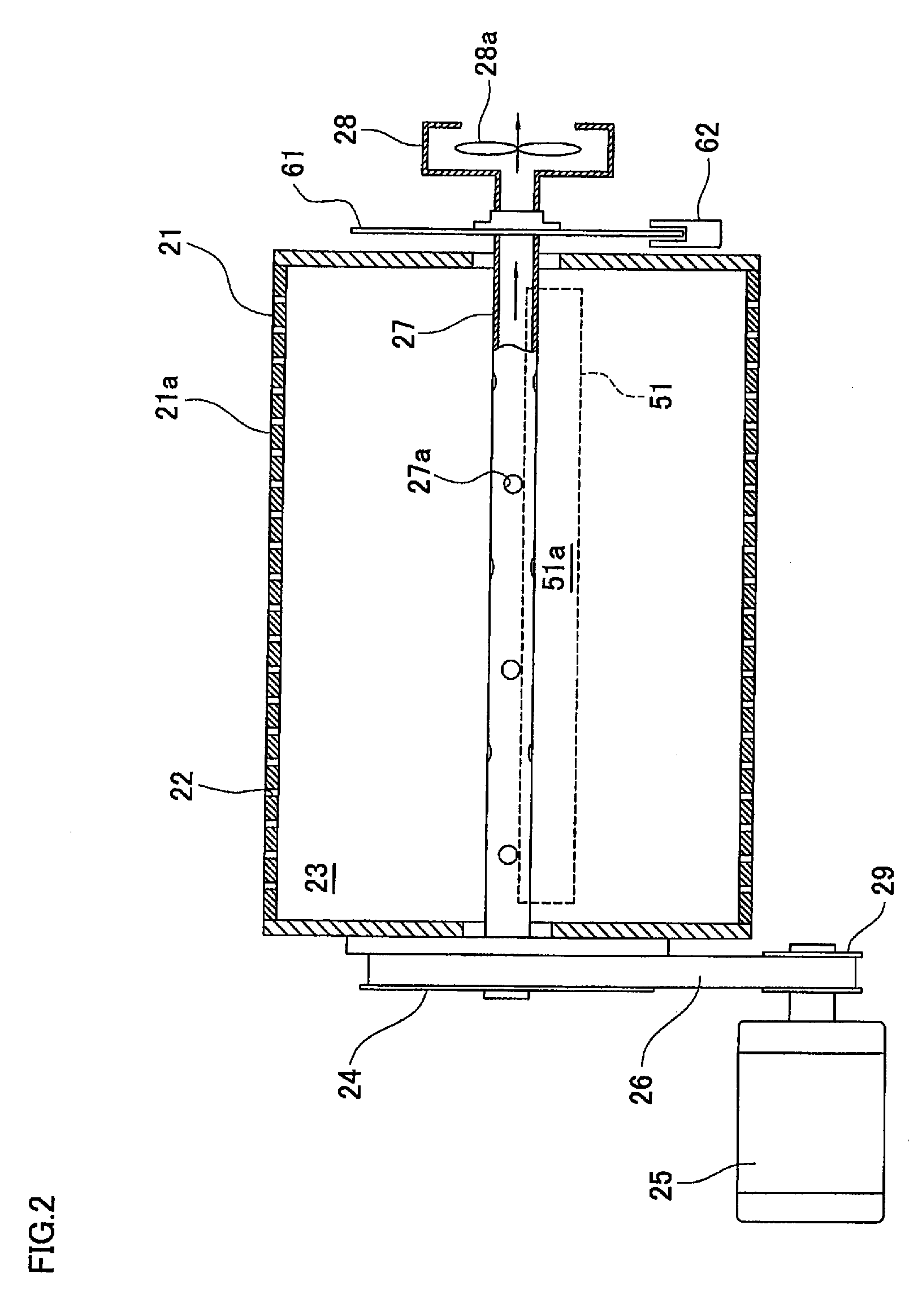
[0017]The following describes, with reference to FIG. 1, an inkjet printer of Embodiment 1, according to the present invention. An inkjet printer 1 serving as an image recording apparatus is a color inkjet printer, and includes a sheet conveyance mechanism 20, a supply mechanism 40, an ejection mechanism 50, and a control device 10. The sheet conveyance mechanism 20 has four inkjet heads 2 each serving as a record head, and a drum 21 having a cylindrical outer circumferential surface 21a. The supply mechanism supplies a sheet to the outer circumferential surface 21a, at a supply position S1 which is a fixed position nearby the lower end of the drum 21 in the inkjet printer 1. The ejection mechanism 50 separates, from the outer circumferential surface 21, the sheet having reached at the separating position S2 nearby the upper end of the drum 21, and ejects the sheet via an ejection path 43. The control device 10 serves as a control unit for controlling operations of these members. Th...

embodiment 2

[0047]Next, Embodiment 2 of the present invention is described with reference to FIG. 4 to FIG. 6. Note that the structure of the present embodiment is essentially the same as that of the foregoing Embodiment 1 except for the sheet conveyance mechanism. The following therefore mainly describes the sheet conveyance mechanism and explanation for the rest of the members are omitted here.

[0048]As shown in FIG. 4 and FIG. 5, the sheet conveyance mechanism of an inkjet printer 101 of the present embodiment serving as an image recording apparatus includes: a drum 121 having a cylindrical outer circumferential surface 121. The supply position S1 and the separating position S2 are the same as those in the printer 101 of Embodiment 1. The drum 121 has a pipe-like shape and the axial direction thereof conforms with a direction perpendicular to the surface of the FIG. 4. The both ends of the drum 121 is closed. The centers of the both closed ends of the drum 21 are connected with each other via...


PUM


Abstract

An image recording apparatus of the present invention includes a conveyance mechanism having a circumferential wall. On the circumferential wall are formed suction holes which communicate an internal space inside the circumferential wall with the outside of the circumferential wall. A recording medium is placed on the outer circumferential surface of the circumferential wall, and is conveyed on the outer circumferential surface in a direction of the rotation of the circumferential wall. A suction unit sucks the air in the internal space to create an air flow from the outside of the circumferential wall to the internal space via the suction holes. A recording medium ejection path branches off from the outer circumferential surface at a separating position which is at the most downstream position of a record head or a position further from the supply position S1 than the most downstream position from the supply position. A blocker positioned in the internal space successively faces an inner opening of at least one of the suction holes having reached the separating position with the movement of the circumferential wall, so as to block the inner opening of the at least one of the suction holes.

Description

CROSS REFERENCE TO RELATED APPLICATION[0001]The present application claims priority from Japanese Patent Application No. 2007-216642, which was filed on Aug. 23, 2007, the disclosure of which is herein incorporated by reference in its entirety.BACKGROUND OF THE INVENTION[0002]1. Field of the Invention[0003]The present invention relates to an image recording apparatus which records an image on a recording medium.[0004]2. Description of the Related Art[0005]Japanese Unexamined Patent Publication No. 175341 / 1998 (Tokukaihei 10-175341) discloses a printer including a conveyance mechanism having a drum. Rotation of the drum carrying a sheet on its outer circumferential surface conveys the sheet in the circumferential direction along the outer circumferential surface. In such a conveyance mechanism, the drum is provided with suction holes which communicate the outside of the drum with the internal space of the same. This drum is rotatably supported by a pipe whose internal space is commun...

Claims


Application Information

Patent Timeline
Patent Type & Authority Applications(United States)
IPC IPC(8): B41J2/01
CPCB41J15/165B41J15/042B41J13/226B65H5/226B65H2406/3614
Inventor OKADA, GORO
Owner BROTHER KOGYO KK
Learn More