
Mobile terminal unit, display method, display program, and recording medium

a technology of mobile terminals and display methods, applied in the direction of television systems, electric apparatus casings/cabinets/drawers, instruments, etc., can solve the problem of ineffective utilization of display screens that can be pulled out to be increased in siz

Active Publication Date: 2009-02-26
UNIFIED INNOVATIVE TECH
View PDF5 Cites 143 Cited by
  • Summary
  • Abstract
  • Description
  • Claims
  • Application Information

AI Technical Summary

Benefits of technology

[0010]The present invention is in view of the foregoing problems, and has as an object to provide a mobile terminal unit by which a pullout display to be pulled out from a body is utilized efficiently, a display method, a display program, and a recording medium.
[0014]Accordingly, the mobile terminal unit produces an advantageous effect that the pullout display is utilized more effectively.
[0016]With this method, the same advantageous effect as that produced by the mobile terminal unit of the present invention is produced.
[0019]This produces an advantageous effect that the pullout display, which is to be pulled out from the body of the mobile terminal unit, is utilized efficiently in the mobile terminal unit.
[0022]This produces an advantageous effect that the pullout display, which is to be pulled out from the body of the mobile terminal unit, is utilized more efficiently in the mobile terminal unit.

Problems solved by technology

Thus, the display that can be pulled out to be increased in size is not utilized effectively.

Method used


Image

  • Mobile terminal unit, display method, display program, and recording medium
  • Mobile terminal unit, display method, display program, and recording medium
  • Mobile terminal unit, display method, display program, and recording medium

Examples


embodiment 1

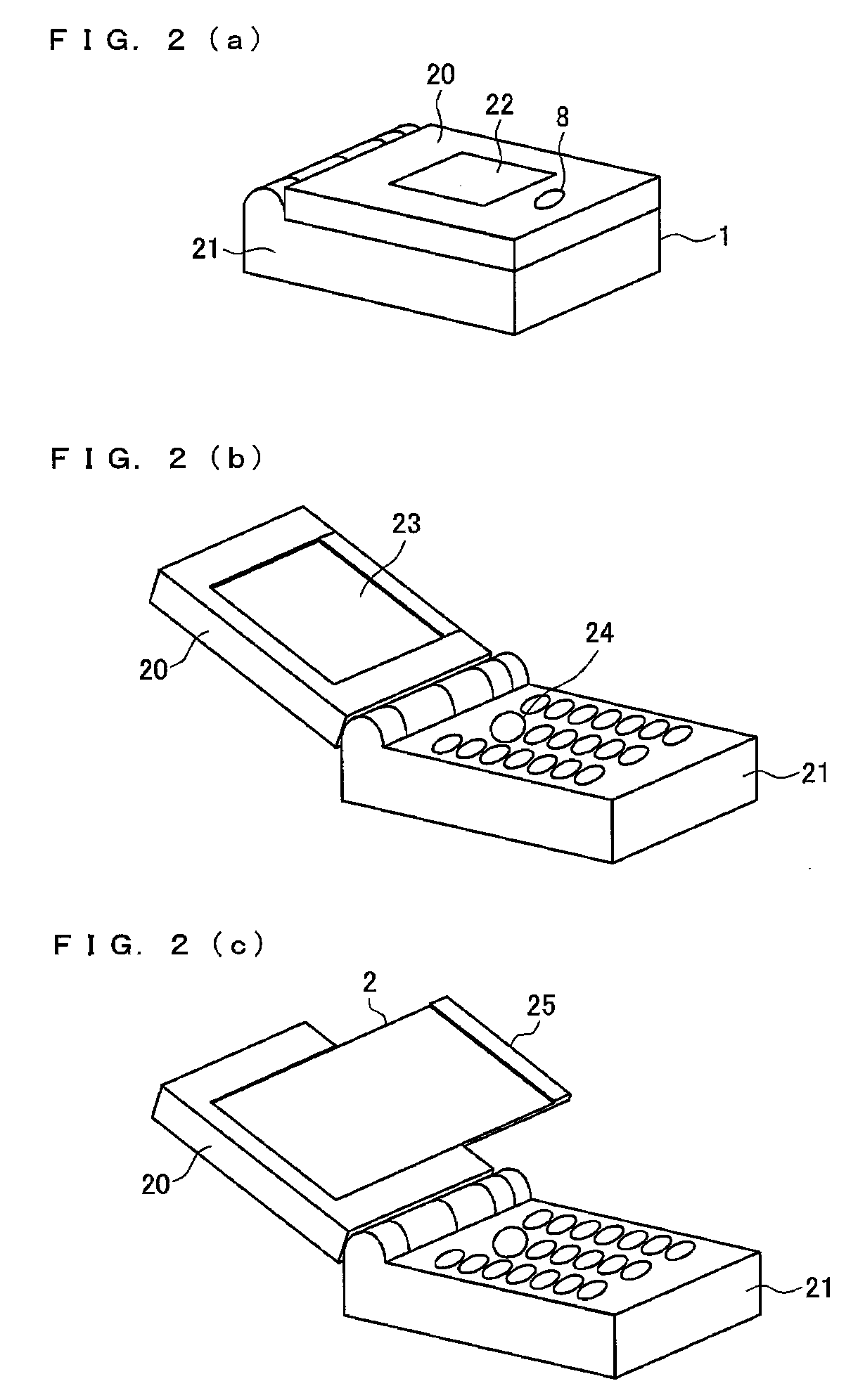
[0156]The following describes Embodiment 1 of the present invention, with reference to FIGS. 1 to 12. In the present embodiment, a mobile terminal unit 1, which is a clamshell-type mobile terminal unit, including a flexible LCD is described. The flexible LCD is slidable by winding.

[0157](Overview of Mobile Terminal Unit 1)

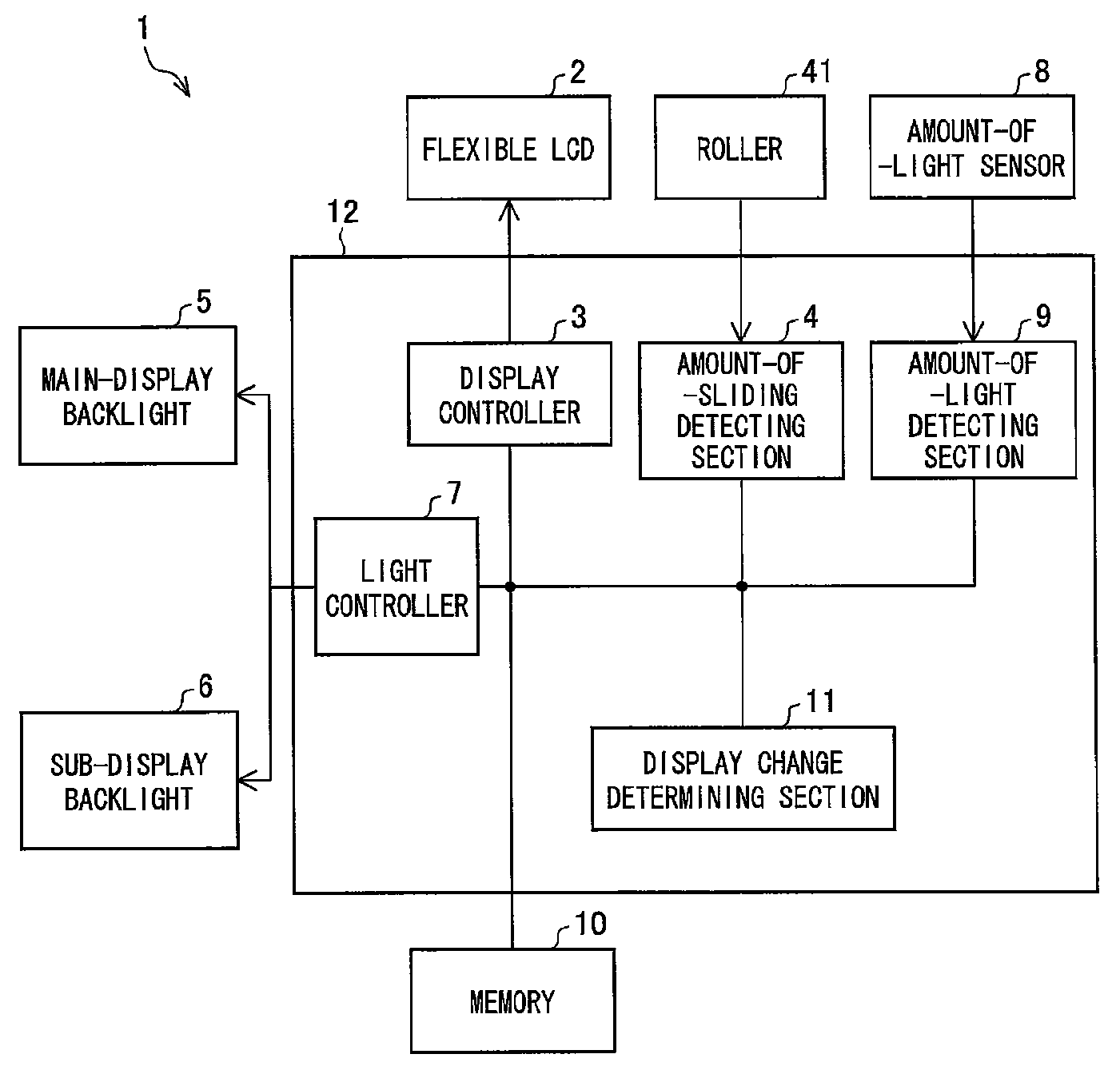
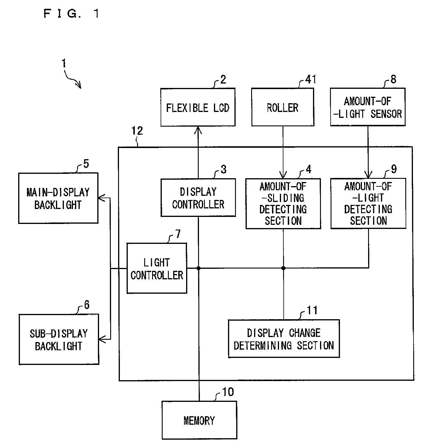
[0158]First of all, the following describes a configuration of main sections of the mobile terminal unit 1 of the present invention, with reference to FIG. 1. FIG. 1 is a block diagram showing the configuration of the main sections of the mobile terminal unit 1 of the present invention.

[0159]As shown in FIG. 1, the mobile terminal unit 1 includes a flexible LCD 2 (pullout display), a main-display backlight 5 (backlight) for a main display, a sub-display backlight 6 for a sub-display, an amount-of-light sensor 8, a memory 10, a controller 12, and a roller 41.

[0160]The foregoing components except for the controller 12 are realized in the form of hardware devices. The...

embodiment 2

[0235]The following describes Embodiment 2 of the present invention, with reference to FIGS. 13 to 16.

[0236]FIG. 13 is a block diagram showing a configuration of main sections of a mobile terminal unit 1a in accordance with Embodiment 2 of the present invention. The mobile terminal unit 1a of the present embodiment further includes, in addition to a winding flexible LCD 2, a motor 131 to automatically, instead of manually, pull out and retract the flexible LCD 2. Specifically, the mobile terminal unit 1a includes the flexible LCD 2, a main-display backlight 5 for a main display, a sub-display backlight 6 for a sub-display, a controller 12a, a motor 131, an operational section 133, and an antenna 135, as shown in FIG. 13.

[0237]Those components except for the controller 12a are realized in the form of hardware devices. The controller 12a, on the other hand, is realizable with software as well as hardware logic. The controller 12a includes a display controller 3, a light controller 7, ...

embodiment 3

[0251]The following describes Embodiment 3 of the present invention, with reference to FIGS. 17 to 20.

[0252]FIG. 17 is a block diagram showing a configuration of main sections of a mobile terminal unit 1b in accordance with Embodiment 3 of the present invention. As shown in this figure, the mobile terminal unit 1b includes a memory 10, a controller 12b, a roller 41, a flexible organic EL 171 (pullout display), and a touch panel 172 (touched-section detecting member). Those components except for the controller 12b are realized in the form of hardware devices. The controller 12b, on the other hand, is realizable with software as well as hardware logic. The controller 12b includes a display controller 3, an amount-of-sliding detecting section 4, an input-by-touch detecting section 173, and a range-of-detection setting section 174, as shown in FIG. 17.

[0253](Overview of the Mobile Terminal Unit 1b)

[0254]In the mobile terminal unit 1b, the flexible organic EL 171 functions as a display p...


PUM


Abstract

A flexible LCD (2) is a flexible display. The flexible LCD (2) is pulled out from an upper cabinet to change a display area of the flexible LCD (2). An amount-of-sliding detecting section (4) measures the pullout amount (amount of sliding) of the flexible LCD (2) when the flexible LCD (2) is pulled out from a mobile terminal unit (1) or is retracted into the mobile terminal unit (1). A display controller (3) causes the flexible LCD (2) to display in a manner responsive to the amount of sliding that is measured by the amount-of-sliding detecting section (4). The foregoing makes it possible to utilize effectively the display having a display area that is revealed when the display is pulled out.

Description

TECHNICAL FIELD[0001]The present invention relates to a mobile terminal unit with a pullout display that is to be pulled out, a display method, a display program, and a recording medium.BACKGROUND ART[0002]Over the recent years, mobile terminal units such as mobile phones have been improved in functionality. For example, there have been developed mobile phones with which it is possible to enjoy not only audio communications but also communications using texts or images, such as sending / receiving electronic mails and browsing the Internet. To make text information or image information viewable on the mobile phones, upsizing of displays has been demanded. At the same time, smaller and lighter terminals have been demanded to make the terminals easy to carry.[0003]To meet the demands, there have been known techniques for upsizing a display area of a display while keeping the body of the mobile terminal small in size.[0004]For example, Publication 1 discloses a mobile terminal unit that ...

Claims


Application Information

Patent Timeline
Patent Type & Authority Applications(United States)
IPC IPC(8): H04N5/655H05K5/02G09G3/20G09G3/34G09G3/36H04M1/00H04M1/02H04M1/22
CPCG02F1/133305H04M2250/22G06F1/1616G06F1/1624G06F1/1647G06F1/1652G06F1/1677G06F1/1684G06F1/1688G06F3/1423G06F2200/1614G09G3/3406G09G2330/021G09G2340/0492G09G2360/144H04M1/0216H04M1/0268G02F1/133308H04B1/38
Inventor MATSUSHITA, YOSHITERUHONDA, MASANORISUZUKITAKEMOTO, MINORU
Owner UNIFIED INNOVATIVE TECH
Learn More