Backward congestion notification

a technology of backward congestion and notification, applied in the field of backward congestion notification, can solve the problems of increasing the difficulty of controlling network congestion in an acceptable manner, increasing the difficulty of buffer size, and causing buffers to fill up very quickly

Active Publication Date: 2009-02-26
CISCO TECH INC
View PDF99 Cites 117 Cited by
  • Summary
  • Abstract
  • Description
  • Claims
  • Application Information

AI Technical Summary

Problems solved by technology

As the speed of network traffic increases, controlling network congestion in an acceptable manner becomes increasingly challenging.
This is true in part because it is not economically feasible to increase buffer sizes in proportion to the higher network speeds.
High speed, coupled with proportionally smaller buffer sizes and low latency, causes buffers to fill up very quickly when congestion arises.

Method used


Image

  • Backward congestion notification
  • Backward congestion notification
  • Backward congestion notification

Examples


example embodiments

[0022]In this application, numerous specific details are set forth in order to provide a thorough understanding of the present invention. It will be obvious, however, to one skilled in the art, that the present invention may be practiced without some or all of these specific details. In other instances, well known process steps have not been described in detail in order not to obscure the present invention.

[0023]Reference will now be made in detail to some specific examples of the invention, including the best modes contemplated by the inventor for carrying out the invention. Examples of these specific embodiments are illustrated in the accompanying drawings. While the invention is described in conjunction with these specific embodiments, it will be understood that it is not intended to limit the invention to the described embodiments. On the contrary, it is intended to cover alternatives, modifications, and equivalents as may be included within the spirit and scope of the invention...


PUM


Abstract

In one embodiment, an apparatus comprises a network interface system having at least one input port configured for receiving frames and a logic system comprising at least one logic device. The logic system may be configured to perform the following functions: determining a source address and a destination address of a frame received at an ingress port; calculating a flow hash based at least upon the source address and the destination address; forming a congestion management (“CM”) tag that includes the flow hash; inserting the CM tag in the frame; and forwarding the frame to the destination address.

Description

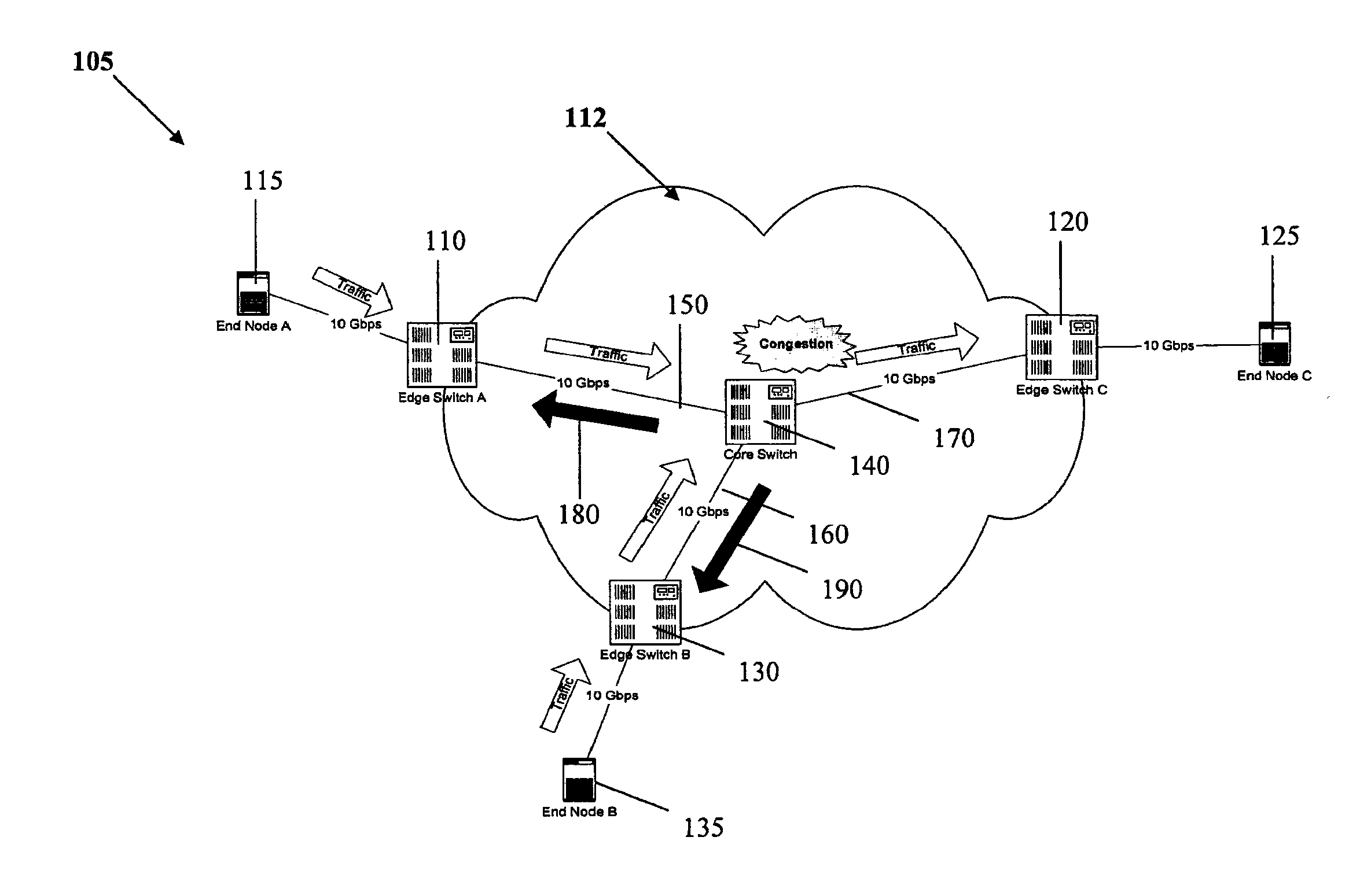
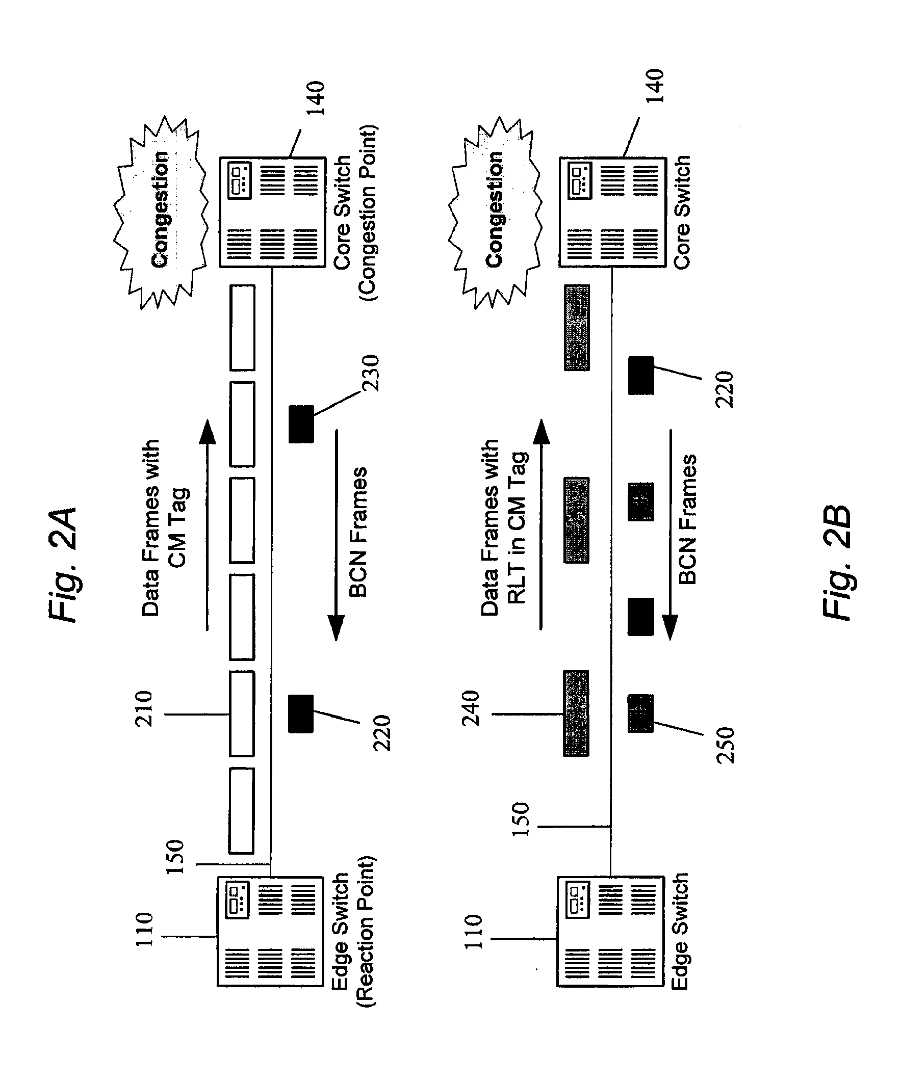
BACKGROUND OF THE INVENTION[0001]As the speed of network traffic increases, controlling network congestion in an acceptable manner becomes increasingly challenging. This is true in part because it is not economically feasible to increase buffer sizes in proportion to the higher network speeds. High speed, coupled with proportionally smaller buffer sizes and low latency, causes buffers to fill up very quickly when congestion arises.[0002]Some examples of high-speed, low latency networks having relatively small buffers, which will be referred to herein as Data Center Ethernet (“DCE”) or the like, are described below. Many of the congestion management challenges of DCE networks are shared by other networks, including but not limited to Fibre Channel networks and high-speed Ethernet. It would be very desirable to implement methods and devices that address at least some of the shortcomings of the prior art.BRIEF DESCRIPTION OF THE DRAWINGS[0003]FIG. 1 is a network diagram illustrating a ...

Claims


Application Information

Patent Timeline
Patent Type & Authority Applications(United States)
IPC IPC(8): H04L12/26
CPCH04L47/10H04L47/11H04L47/33H04L47/263H04L47/17
Inventor BERGAMASCO, DAVIDEDUTT, DINESH
Owner CISCO TECH INC
Why Eureka
Try Eureka