System and method for collecting backscattered electrons in an x-ray tube

a backscattered electron and electron collection technology, applied in the field of electron collectors, can solve the problems of reducing the image quality of x-ray images, increasing undesirable exposure to x-ray radiation, and excessive heat generation,

Inactive Publication Date: 2009-02-26
GENERAL ELECTRIC CO
View PDF26 Cites 5 Cited by
  • Summary
  • Abstract
  • Description
  • Claims
  • Application Information

AI Technical Summary

Problems solved by technology

Excess heat generation adversely affects the durability of the x-ray tube.
Furthermore, in addition to transferring thermal energy to the x-ray tube's internal components, the impact of backscattered electrons also produces off-focus x-ray radiation that may increase undesirable exposure to x-ray radiation and diminish x-ray image quality.

Method used


Image

  • System and method for collecting backscattered electrons in an x-ray tube
  • System and method for collecting backscattered electrons in an x-ray tube
  • System and method for collecting backscattered electrons in an x-ray tube

Examples


Embodiment Construction

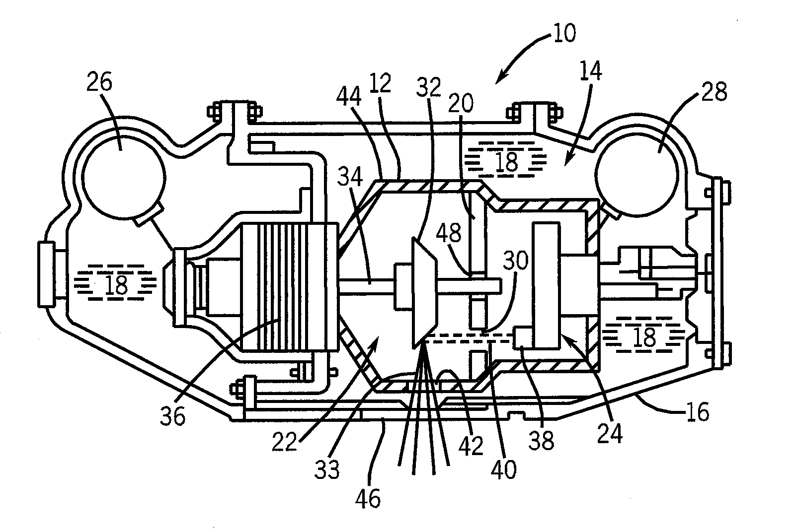
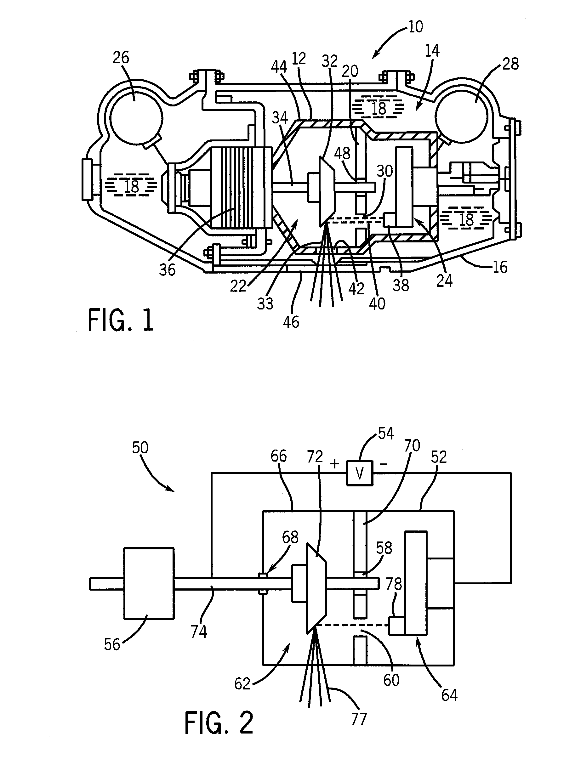
[0019]FIG. 1 is a cross-sectional view of an exemplary embodiment of an x-ray tube assembly 10. The x-ray tube assembly 10 includes a substantially evacuated vacuum vessel 12 that is situated in a chamber 14 defined within a casing 16. The vacuum vessel 12 is constructed to endure very high temperatures and includes an anode assembly 22, a cathode assembly 24, and an electron collector assembly 20 positioned between the anode assembly 22 and the cathode assembly 24. The casing 16 may be lined with lead to shield and prevent any extraneous x-ray radiation from straying from the x-ray tube assembly 10. The chamber 14 within the casing 16 may be filled with a heat absorbing cooling fluid 18 such as, for example, a dielectric oil. The x-ray tube assembly 10 further includes a high voltage anode receptacle 26 and a high voltage cathode receptacle 28 that serve as connection points for an electrical power supply (not shown) for powering the x-ray tube assembly 10. The anode assembly 22 is...


PUM


Abstract

A system and method for collecting backscattered electrons within a substantially evacuated vessel containing both an electron-emitting cathode assembly and an electron-attracting anode assembly. The system and method comprises an electron collector assembly including a first plate, a second plate, an internal member, a fluid inlet, and a fluid outlet. The first plate is mounted within the vessel closest to the anode assembly. The second plate is mounted within the vessel closest to the cathode assembly. The internal member is positioned between the first plate and the second plate, and includes an internal conduit for conveying a heat absorbing cooling fluid therethrough.

Description

CROSS-REFERENCE TO RELATED APPLICATIONS[0001]This application is a continuation-in-part of and claims priority to U.S. patent application Ser. No. 11 / 306,233, filed on Dec. 20, 2005, the disclosure of which is incorporated herein by reference.BACKGROUND OF THE INVENTION[0002]The present disclosure relates generally to electron collectors, and more particularly to a system and method for collecting backscattered electrons within, for example, a substantially evacuated vessel, such as an x-ray tube.[0003]An x-ray tube generally includes a cathode assembly and an anode assembly disposed within a vacuum vessel. The anode assembly includes an anode. The anode commonly includes a stationary or a rotating target with a target track or impact zone fabricated on an outer surface thereof. The target track or impact zone is generally fabricated from a refractory metal with a high atomic number, such as tungsten or a tungsten alloy. The cathode assembly is positioned at some distance from the a...

Claims


Application Information

Patent Timeline
Patent Type & Authority Applications(United States)
IPC IPC(8): H01J35/10
CPCH01J35/16H01J2235/1216H01J2235/1237H01J2235/168H01J2235/1262H01J2235/1283H01J2235/125
Inventor SUBRAYA, MADHUSUDHANA T.HEBERT, MICHAEL SCOTTSTEINLAGE, GREGORY ALAN
Owner GENERAL ELECTRIC CO
Why Eureka
Try Eureka