Automated body fluid drain control apparatus and method

a technology of automatic body fluid drainage and control apparatus, which is applied in the direction of catheters, wound drains, contraceptive devices, etc., can solve the problems of inability to easily control the fluid drainage rate of these devices, the rate at which the fluid drains is not linear, and the patient can be irreversibly injured or fatally injured

Active Publication Date: 2009-02-26
BECKERSMITH MEDICAL
View PDF4 Cites 15 Cited by
  • Summary
  • Abstract
  • Description
  • Claims
  • Application Information

AI Technical Summary

Benefits of technology

[0011]Thereafter, the CSF fluid drains through the proximal valve into the first collection chamber through the use of gravity. As the fluid drains into the first chamber, the volume of the first chamber is constantly measured by the measuring device. Once the microprocessor determines that the first chamber is filled to a preselected level at any time prior to the expiration of the then applicable preselected

Problems solved by technology

None of these devices are able to easily control the drainage rate of the fluid as a function of time.
The amount of drainage must be regulated, as if there is too much drainage, a patient can be irreversibly injured or can be fatally injured.
Unfortunately, the rate at which the CSF drains is not

Method used


Image

  • Automated body fluid drain control apparatus and method
  • Automated body fluid drain control apparatus and method
  • Automated body fluid drain control apparatus and method

Examples


Embodiment Construction

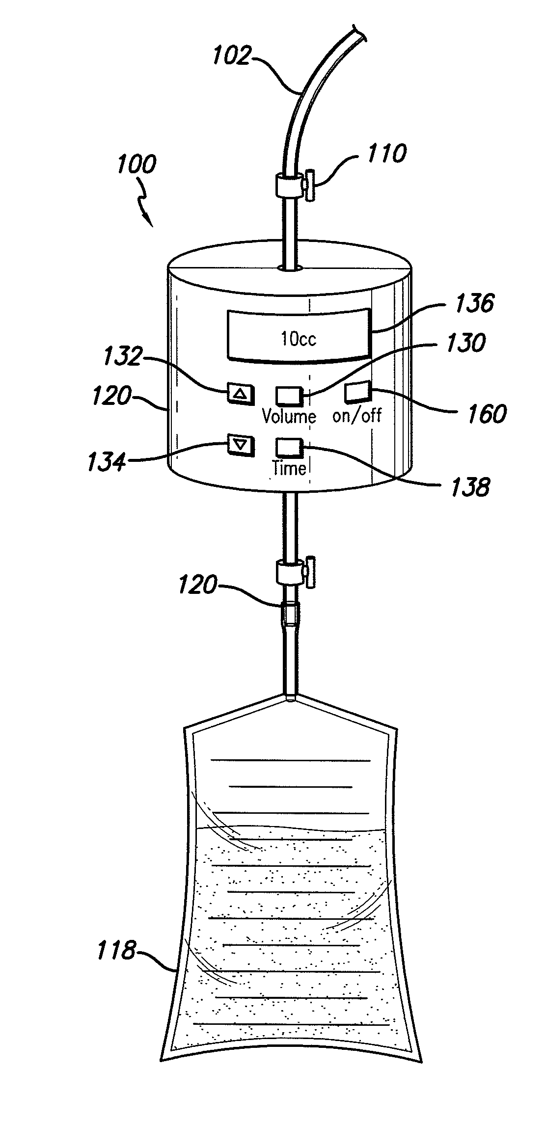
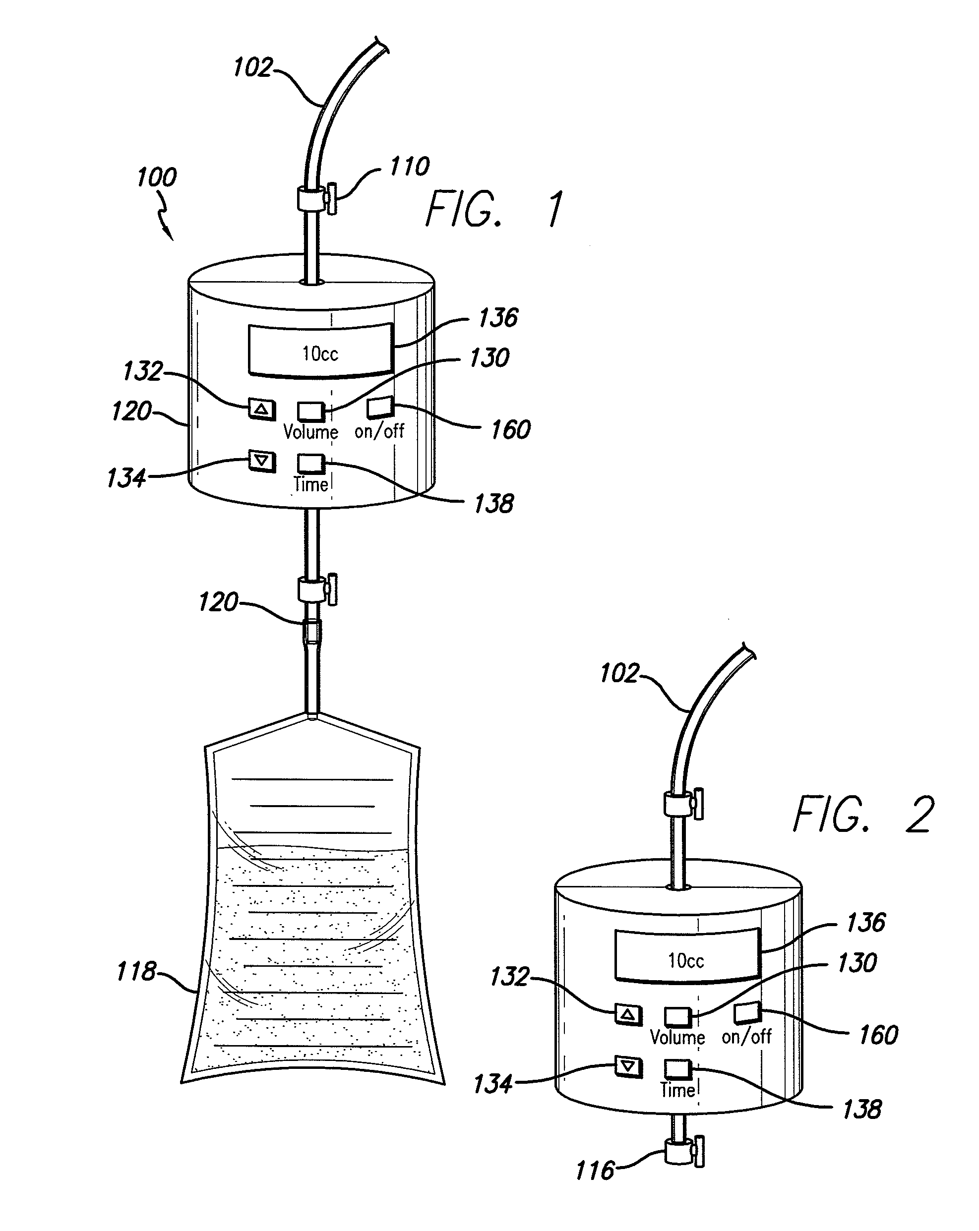
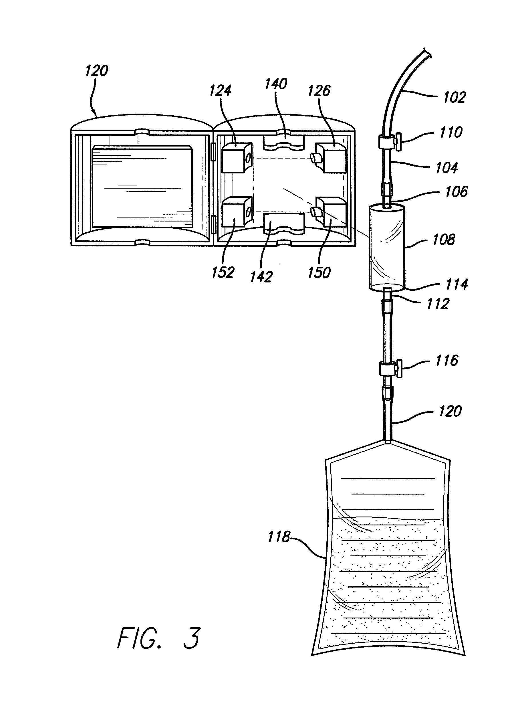
[0007]In a preferred embodiment of the present invention, an automated fluid collection apparatus comprises a first tube having a first end connected to a drain that has been inserted into a patient's subarachnoid region and a second end connected to an opening at the proximal end of a first collection chamber. The first collection chamber also has an opening at the distal end thereof. In one embodiment the chamber has a first valve or first controllable closing mechanism proximate the opening at the proximal end and a second valve or controllable closing mechanism at the distal opening thereof. In another embodiment, there is a second tube having a first end and a second end, whereby the first end is connected to the opening at the distal end of the collection chamber. In the preferred embodiments of the present invention, the first and second valves may be located on the first and second tubes respectively or on the proximal and distal ends of the first chamber. In one preferred e...


PUM


Abstract

Described herein is an automated fluid drain control apparatus and method which comprises a first collection chamber which is connected to a drain that has been inserted into the subarachnoid area in lumbar region of the body. The volume of fluid into the first collection chamber is controlled as a function of time by being constantly measured such that too much fluid will not be drained from the body.

Description

[0001]This application claims the benefit of U.S. Provisional Application No. 60 / 966,132 filed Aug. 25, 2007, which is herein incorporated by reference in its entirety.FIELD OF THE INVENTION[0002]The present invention relates generally to fluid collection devices from the body. More specifically, this invention relates to cerebrospinal fluid drainage and collection devices and methods for controlling the drainage.BACKGROUND OF THE INVENTION[0003]Body fluid drains and containers are well known in the art. For example, there are collection devices for urine and others that drain and collect spinal fluid. None of these devices are able to easily control the drainage rate of the fluid as a function of time.[0004]In connection with the drainage of cerebrospinal fluid (“CSF”), for most people, the body produces 450 ccs of CSF over a 24 hour period which fills the subarachnoid space in the body. There are many instances where it may be advisable and / or necessary for some of the CSF to be d...

Claims


Application Information

Patent Timeline
IPC IPC(8): A61M1/00
CPCA61M1/0031A61M27/006A61M2202/0464A61M1/0021A61M2205/3386A61M2205/44A61M2205/3382A61M1/70A61M1/74
Inventor ECKERMANN, JAN
Owner BECKERSMITH MEDICAL
Why Eureka
Try Eureka