Intralumenal contact sensor

a contact sensor and intralumenal technology, applied in the field of intralumenal contact sensors, can solve the problems of not being able to directly or indirectly visualize the treatment site, preventing the treatment site, and inability to precisely position the catheter

Inactive Publication Date: 2005-09-13
CARDIOFOCUS INC
View PDF43 Cites 341 Cited by
  • Summary
  • Abstract
  • Description
  • Claims
  • Application Information

AI Technical Summary

Benefits of technology

[0008]The balloon member of the catheter serves to force any remaining body fluids, such as blood, away from the treatment site. The absence of body fluids, such as blood, causes an increase in the amount of reflected light from the tissue surface, thereby indicating to the operator when the instrument is advantageously positioned against the treatment site. The invention is particularly useful in cardiac therapy in creating annular conduction blocks in atrial chamber issue, e.g. centered about but at a defined distance from a pulmonary vein orifice or coronary sinus orifice, to eliminate aberrant wave conduction.
[0012]In one embodiment of the present invention, the photoablation instrument includes an expandable balloon member adapted to surround the optical assembly upon inflation. Injection of a solution or gas expands the balloon, thereby forcing blood and / or other body fluids from the tissue site. Preferably, the balloon member can be inflated with deuterium oxide or deuterated water, such that the inflated balloon provides a low loss transmission pathway for radiation between the optical assembly and the tissue surface. Deuterium oxide provides the advantage that it absorbs less energy from the transmitted energy, thereby preventing the balloon from becoming heated.

Problems solved by technology

Photothermal treatment of tissue has certain drawbacks associated with the positioning of the catheter and the fiber optic cable.
This misdirected energy may also prevent the treatment site from receiving what is believed to be the appropriate dose of therapeutic energy.
These drawbacks are often associated with not being able to directly or indirectly visualize the treatment site.
This method allows for some uncertainty in the exact placement of the fiber optic cable and catheter and does not inform the physician when the catheter is in contact with tissue.
However, blood and other body fluids can obstruct the view of the physician, which can lead to imprecise positioning of the catheter.
Either method does not allow the physician to always predict when the distal end of the catheter is in contact with the site that requires treatment.

Method used


Image

  • Intralumenal contact sensor
  • Intralumenal contact sensor
  • Intralumenal contact sensor

Examples


Embodiment Construction

[0022]The features and other details of the invention will now be more particularly described and pointed out in the claims. It will be understood that the particular embodiments of the invention are shown by way of illustration and not as limitations of the invention. The principle features of this invention can be employed in various embodiments without departing from the scope of the invention.

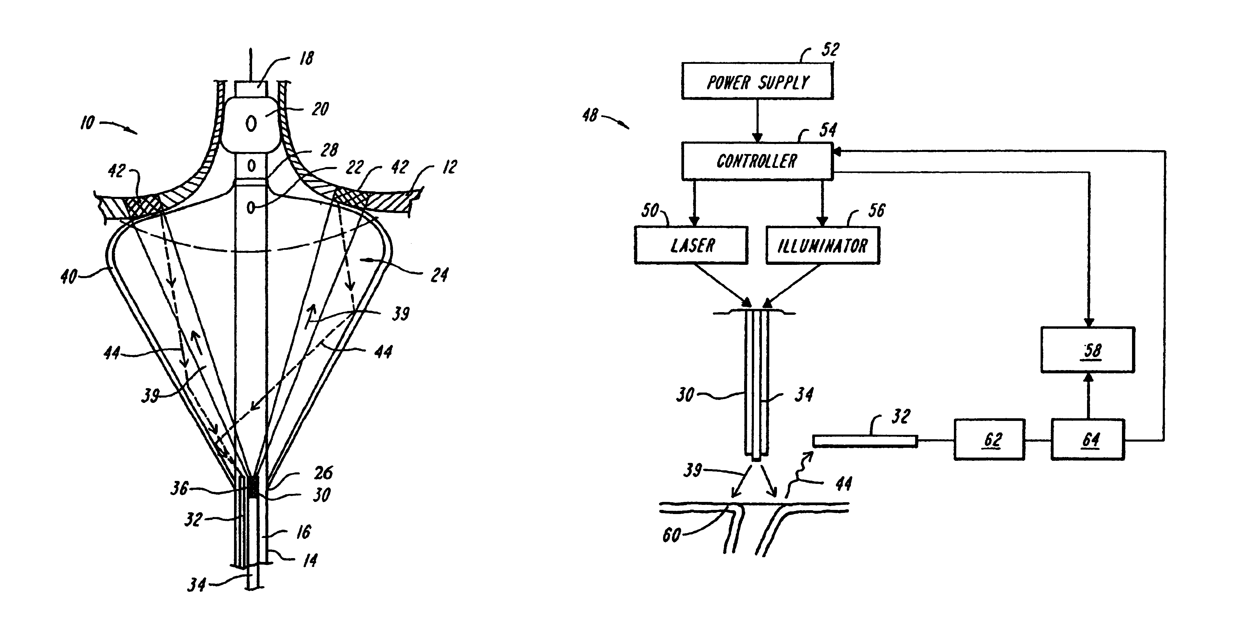
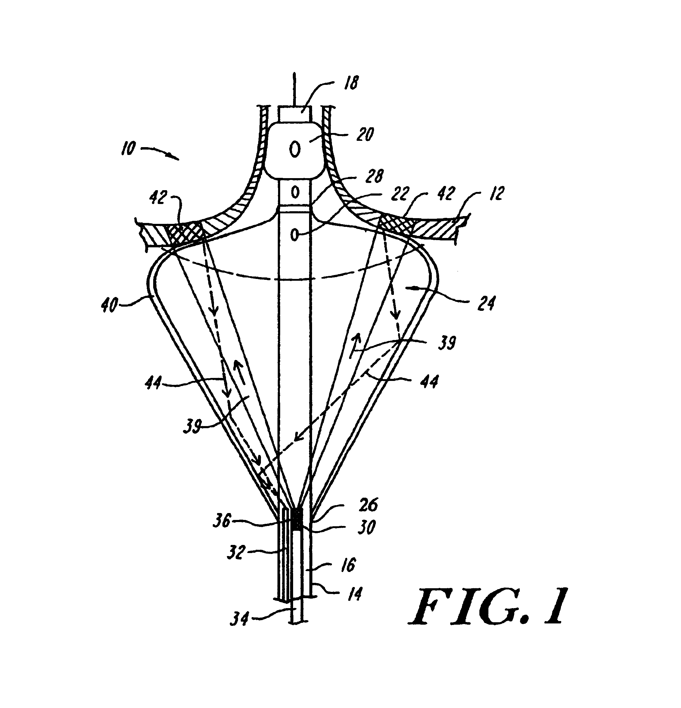
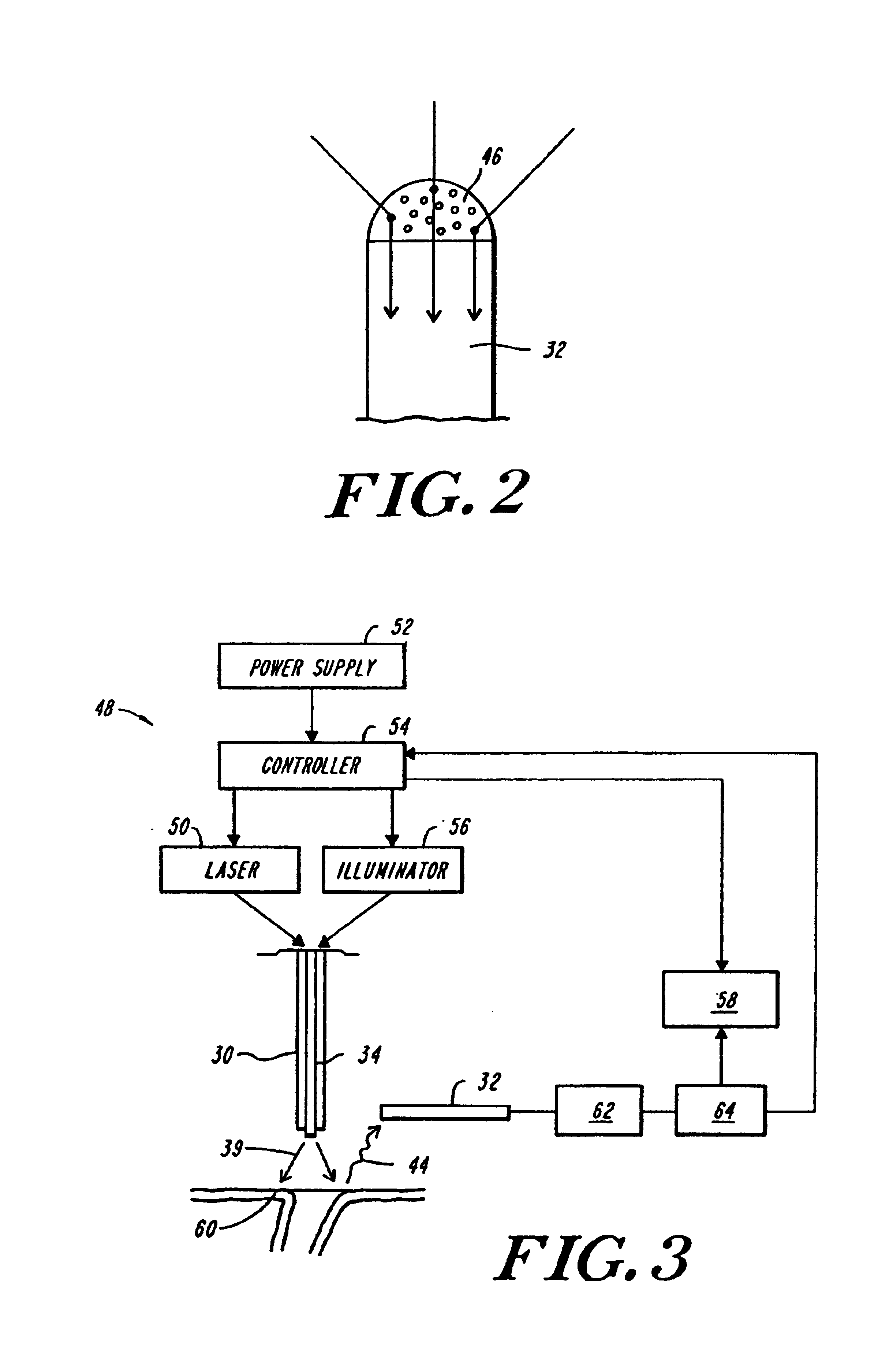
[0023]The present invention is based, at least in part, on a discovery that the present invention can be used for inducing hyperthermia, coagulation or phototherapeutic processes in tissue, e.g., ablation, degradation, or destruction of tissue, at a specified site in tissue without harming the surrounding tissue. The results are surprising and unexpected since the efficiency and efficacy of coherent light is generally diminished by light scatter, formation of “hot spots” due to inefficient light scatter, by the limitation that the light emitted from an optical fiber continues in a straight ...


PUM


Abstract

An apparatus and method for phototherapy are described in which laser light or other radiation is projected from within a catheter, through a balloon member, and toward the surface of tissue. The light reflected from body fluids or the tissue surface is captured by a collecting device located within the catheter, e.g., within the balloon member, and the intensity of the reflected light is ascertained. The apparatus and method provides for accurately positioning the apparatus against the tissue treatment site.

Description

RELATED APPLICATIONS[0001]This application is a continuation application of U.S. patent application Ser. No. 09 / 616,275 filed Jul. 14, 2000, now U.S. Pat. No. 6,626,900, which claims priority to U.S. Ser. No. 09 / 602,420 filed Jun. 23, 2000, now U.S. Pat. No. 6,572,609, which claims priority to U.S. patent application Ser. No. 09 / 357,355 filed on Jul. 14, 1999, now U.S. Pat. No. 6,423,055, the contents of which are incorporated herein by reference.BACKGROUND OF THE INVENTION[0002]Treatment of diseased tissues by various therapies is of vital importance in the medical community. Visualization of the treatment site is preferred; however, medical advances have provided improved methods, such as cardiac catheterization, which permits a physician to perform a medical procedure on the heart without ever directly observing the treatment site.[0003]Cardiac catheterization includes the use of a catheter, which delivers, for example, a fiber optic cable to the treatment site. Transmission of e...

Claims


Application Information

Patent Timeline
Patent Type & Authority Patents(United States)
IPC IPC(8): A61B18/20A61B18/24A61B19/00A61B18/00A61B18/22A61B17/00A61M25/00A61N5/06
CPCA61B18/245A61B2017/00061A61B2018/0097A61B2018/2266A61B2018/2272A61B2019/465A61B2090/065
Inventor SINOFSKY, EDWARD L.FARR, NORMAN E.
Owner CARDIOFOCUS INC
Why Eureka
Try Eureka