Sensors

a technology of sensors and fluids, applied in the field of sensors, can solve the problems of difficult for users to locate and contact with biological fluids, compounding the difficulty of locating and positioning samples, and inability to easily locate the sample port and properly conta

Active Publication Date: 2007-05-17
ABBOTT DIABETES CARE INC
View PDF20 Cites 359 Cited by
  • Summary
  • Abstract
  • Description
  • Claims
  • Application Information

AI Technical Summary

Problems solved by technology

Sample ports of conventional sensors are located on the top (“top fill”), the centered front end (“front-fill”), or a side (“side fill”) of the sensors, which makes it difficult for a user to locate and contact with biological fluid.
Users of such devices may have visual and / or dexterity problems, e.g., resulting from an underlying disease state such as diabetes, further compounding the difficulty in locating the sample port and positioning near a site of biological fluid.
The inability to easily locate the sample port and properly contact the sample to be tested with the sample port may not simply be a minor nuisance, but may have serious consequences.
For example, in attempts to locate the sample port, the sample maybe smeared over the sensor surfaces resulting a difficult to handle sensor.
Sample smearing, and other factors associated with the inability to easily locate the sample port may have other serious consequences as well.
For example, such may deplete the volume of sample available for testing so there may not be a sufficient amount of sample.
A test may not begin and / or erroneous testing results may occur if an insufficient sample volume is present in the sample chamber.
The user may associate both options with significant pain and may therefore elect instead to forego the testing.
For example, a test strip having cone-shaped channel entrance in the center of the front end of the test strip has been developed, but has not adequately addressed the problems and adds complexity to the manufacturing process.

Method used


Image

  • Sensors
  • Sensors
  • Sensors

Examples


Embodiment Construction

[0055] Before the present invention is described, it is to be understood that this invention is not limited to particular embodiments described, as such may, of course, vary. It is also to be understood that the terminology used herein is for the purpose of describing particular embodiments only, and is not intended to be limiting, since the scope of the present invention will be limited only by the appended claims.

[0056] Where a range of values is provided, it is understood that each intervening value, to the tenth of the unit of the lower limit unless the context clearly dictates otherwise, between the upper and lower limit of that range and any other stated or intervening value in that stated range, is encompassed within the invention. The upper and lower limits of these smaller ranges may independently be included in the smaller ranges is also encompassed within the invention, subject to any specifically excluded limit in the stated range. Where the stated range includes one or...


PUM

PropertyMeasurementUnit
distanceaaaaaaaaaa
volumeaaaaaaaaaa
angleaaaaaaaaaa

Abstract

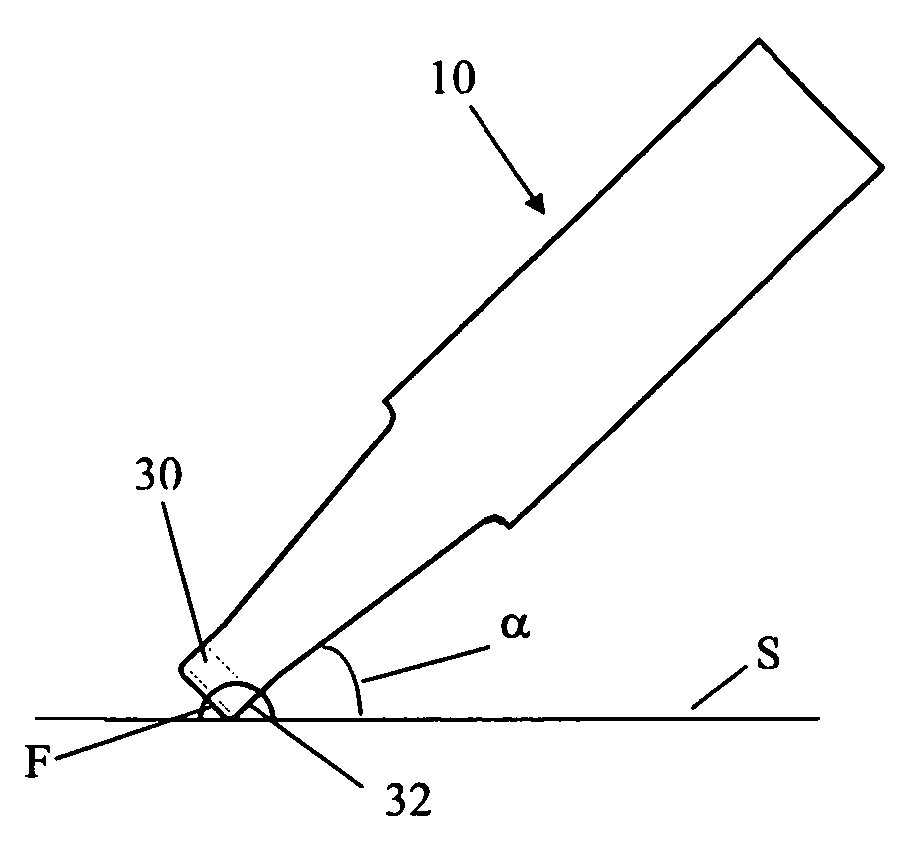
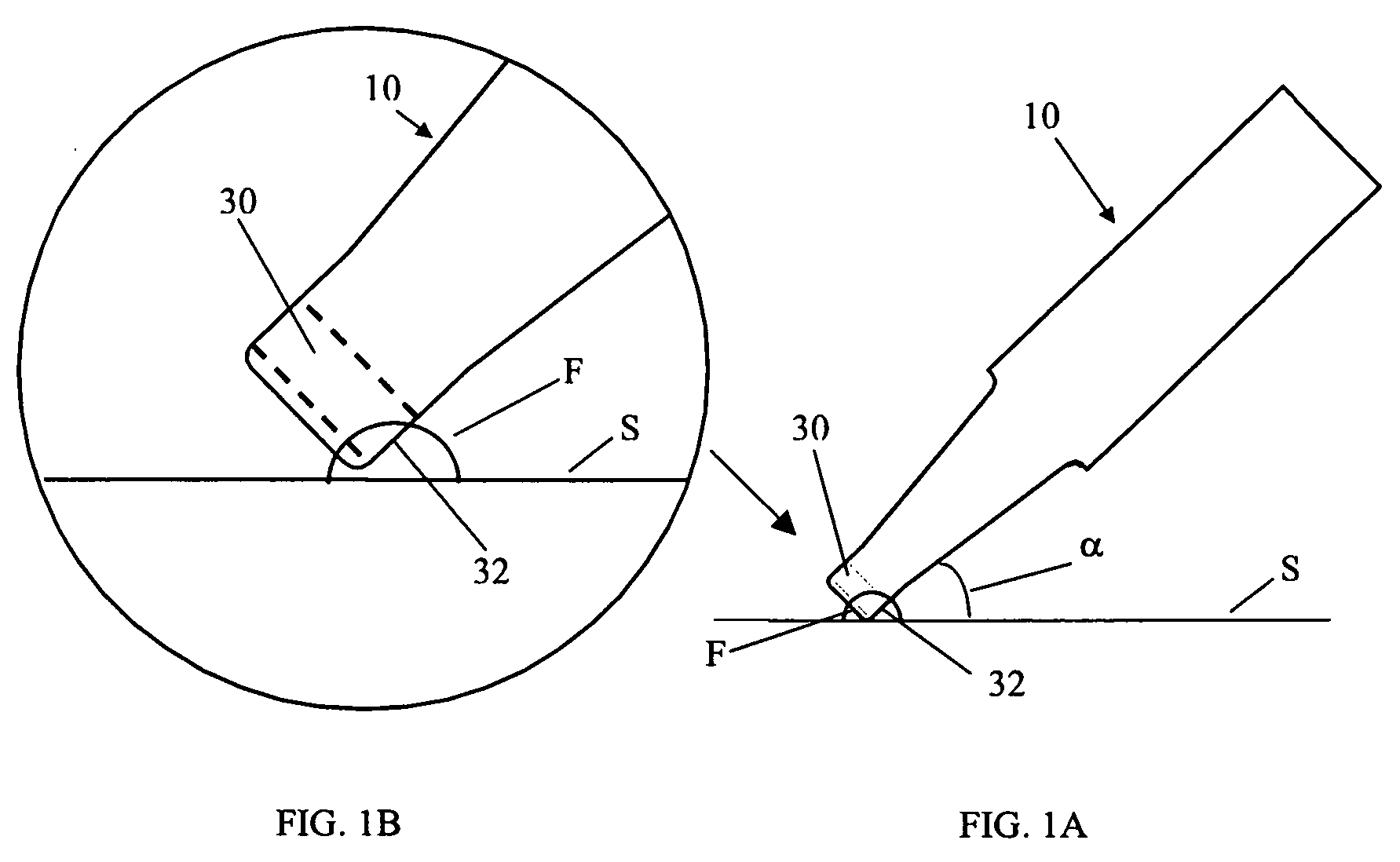
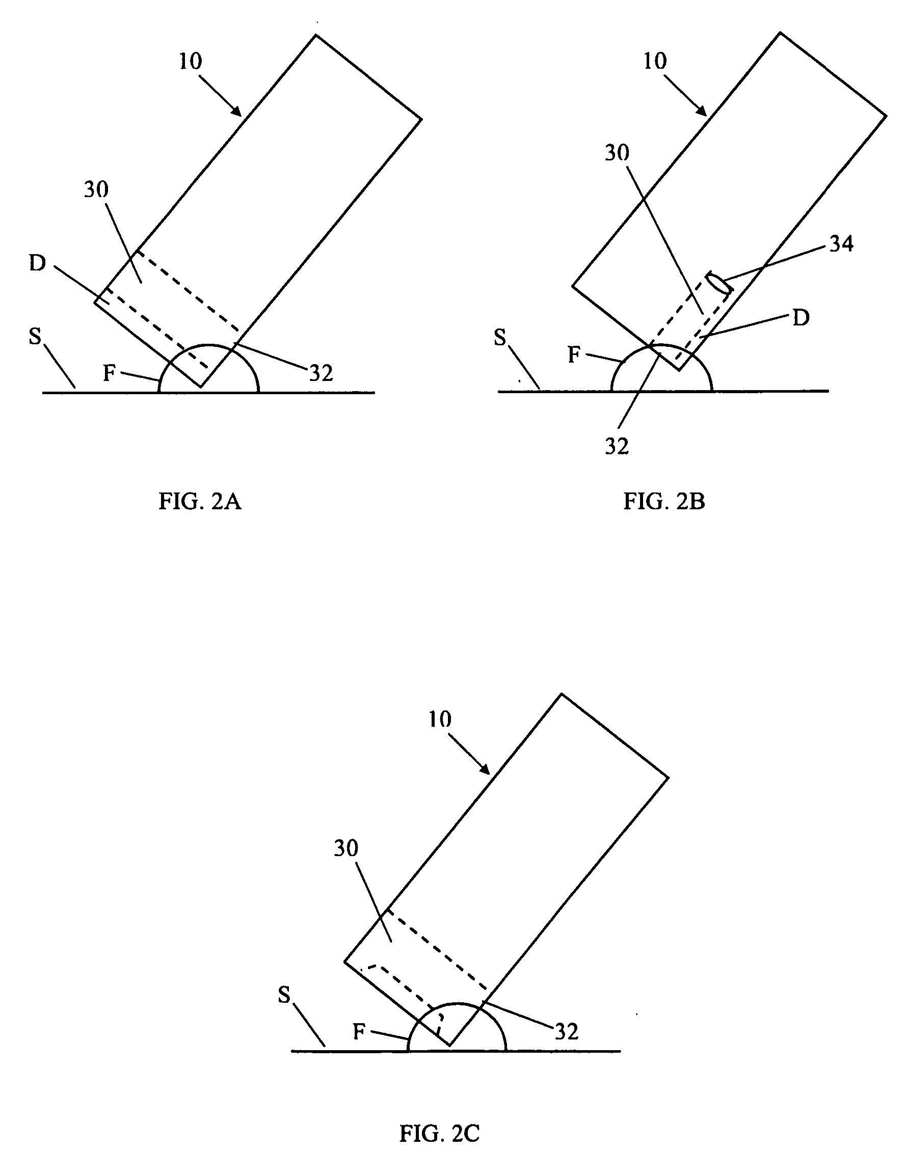
The subject invention provides devices and methods for the analysis of a body fluid. Embodiments include sensors that are sample-fillable by contacting a corner of the sensor to a sample.

Description

BACKGROUND OF THE INVENTION [0001] Analytical sensors, e.g., test strips, are commonly used to determine the presence and concentration of an analyte in biological fluid. Such sensors may be used, for example, to monitor blood glucose levels of diabetic patients. [0002] In using analyte sensors, an opening is created in the skin (e.g., by lancing the skin) to cause a flow of biological fluid from the region. At least a portion of this biological fluid is contacted to a sensor where the concentration of analyte in the fluid is then determined. Specifically, an opening in the skin is produced and an opening (i.e., a sample port) of the sensor is contacted to the expressed biological fluid to bring the fluid into contact with the sample chamber of the sensor where analysis occurs. The sample chamber is in fluid communication with the sample port. [0003] Locating the sample port and contacting it with biological fluid is not without difficulty and becomes an even greater concern as the ...

Claims


Application Information

Patent Timeline
Patent Type & Authority Applications(United States)
IPC IPC(8): G01N33/487
CPCC12Q1/001C12Q1/006G01N33/525G01N33/526G01N27/3272B01L3/502715B01L2200/027B01L2300/0825
Inventor WANG, YISCOTT, STEVE
Owner ABBOTT DIABETES CARE INC
Why Eureka
Try Eureka