Method for Enabling Profile-Based Call Site Tailor-ing Using Profile Gathering of Cloned Functions
- Summary
- Abstract
- Description
- Claims
- Application Information
AI Technical Summary
Problems solved by technology
Method used
Image
Examples
example
[0067]Four clones may be generated for a function f, and separated according to call sites as described above. Profiling in final step 84 yields exemplary results, as shown in Table 1, in which the number of clone-specific calls are shown.
[0068]Clones 1 and 2 represent calls to the function f occurring in normal program operation. Clones 3 and 4 represent calls occurring under abnormal circumstances, e.g., some error condition. It may be helpful to aggregate normal and abnormal profile data by aggregating the four clones to form two classes, and then combining clone-specific profile data of the classes. Classes 1 and 2 aggregate results of normal and abnormal calls to the function f, respectively. The combined data are then displayed as class results. This can be done even if criteria for clone generation were not tailored to create these classes prior to performing decision step 72. The effect is seen from an inspection of Table 1 and Table 2.
TABLE 1Clone 1Clone 2Clone 3Clone 45075...
embodiment 1
ALTERNATE EMBODIMENT 1
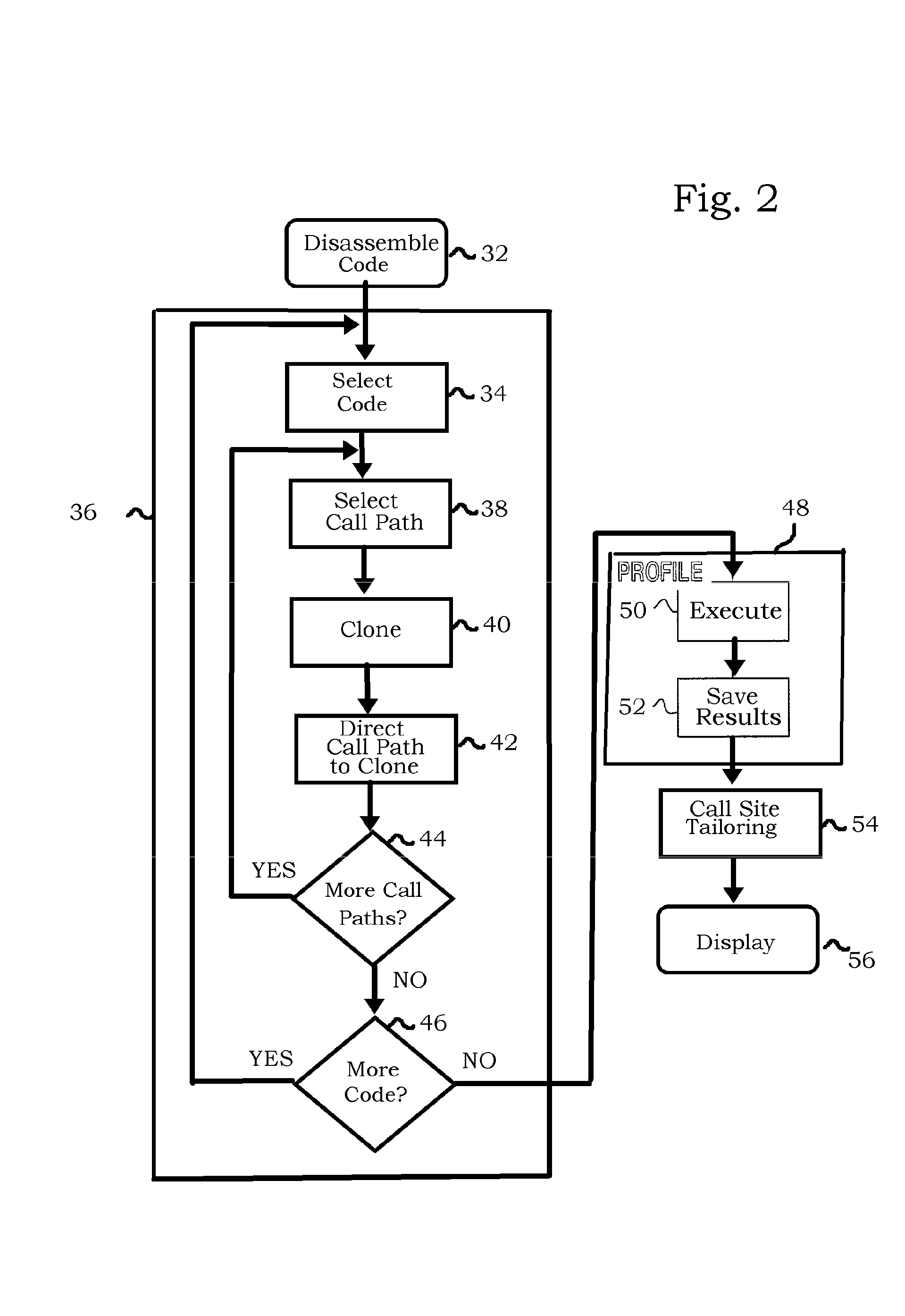
[0090]Reference is now made to FIG. 6, which is a high-level flow chart of a method for gathering profile information from computer program code in accordance with an alternate embodiment of the invention. This embodiment has many steps in common with the embodiment of FIG. 2, which are not repeated. However cloning now is limited by call stack depth, a value determined by the number of functions currently invoked. In this embodiment, after selection of a call site in step 76, control proceeds to decision step 77, where it is determined if the call stack depth relating to the current call site exceeds a predetermined level. If the determination at decision step 77 is affirmative, then control returns to step 76 for selection of a different call site.
[0091]If the determination at decision step 77 is negative, then control proceeds to step 78 in which the function is cloned as in the embodiment of FIG. 2.
[0092]The advantage of this embodiment is that fewer replic...
embodiment 2
ALTERNATE EMBODIMENT 2
[0093]Many programs are very large, or contain code that is rarely executed. In order to expedite gathering of meaningful profiling information, preliminary profiling is carried out in order to identify blocks or functions that meet predefined criteria. Generally, the criteria relate to activity of the blocks or functions. Qualifying code is subjected to further analysis and cloning according to the invention, as described below. Code that fails to qualify may be ignored. Qualifying code may mean hot code, implying that cloning is usually restricted to hot code in this embodiment. However, other criteria could be applied.
[0094]Reference is now made to FIG. 7, which is a high-level flow chart of a method for preliminarily gathering profile information from computer program code in accordance with an alternate embodiment of the invention, referred to as “preprofiling”. Initial step 32 is carried out as described above with reference to FIG. 2. Pre-profiling is re...
PUM
 Abstract
Description
Claims
Application Information
 - R&D
- Intellectual Property
- Life Sciences
- Materials
- Tech Scout
- Unparalleled Data Quality
- Higher Quality Content
- 60% Fewer Hallucinations
Browse by: Latest US Patents, China's latest patents, Technical Efficacy Thesaurus, Application Domain, Technology Topic, Popular Technical Reports.
© 2025 PatSnap. All rights reserved.Legal|Privacy policy|Modern Slavery Act Transparency Statement|Sitemap|About US| Contact US: help@patsnap.com


