Assembling method of bearing unit

a technology of bearing unit and assembly method, which is applied in the direction of bearing unit rigid support, manufacturing tools, mechanical apparatus, etc., can solve the problems of reducing deteriorating productivity, and lowering so as to enhance the efficiency of the assembling work of the bearing unit and improve productivity

Active Publication Date: 2009-03-05
NSK LTD
View PDF3 Cites 3 Cited by
  • Summary
  • Abstract
  • Description
  • Claims
  • Application Information

AI Technical Summary

Benefits of technology

[0022]According to the present invention described above, at the time of assembling the bearing unit, it is unnecessary to check whether or not the engagement pawls are properly formed in the inner circumferential portion of the retainer plate. Accordingly, the efficiency of the assembling work of the bearing unit is enhanced and the productivity can be improved.

Problems solved by technology

Therefore, the efficiency of the assembling work of the bearing unit is lowered and the productivity is deteriorated.
However, in this case, it is necessary to newly prepare the exclusive press machine and further, if dimensions of the bearing are changed, it is impossible for this exclusive press machine to cope with the change in the circumstances.

Method used


Image

  • Assembling method of bearing unit
  • Assembling method of bearing unit
  • Assembling method of bearing unit

Examples


first embodiment

[0037]FIGS. 1 to 6 are views showing the first embodiment of the present invention.

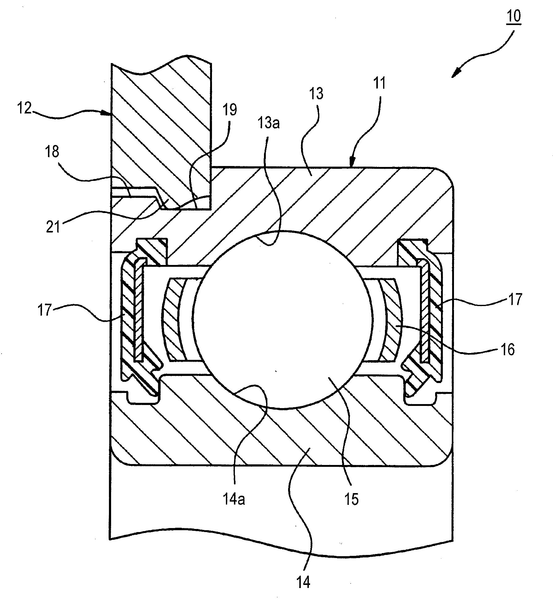
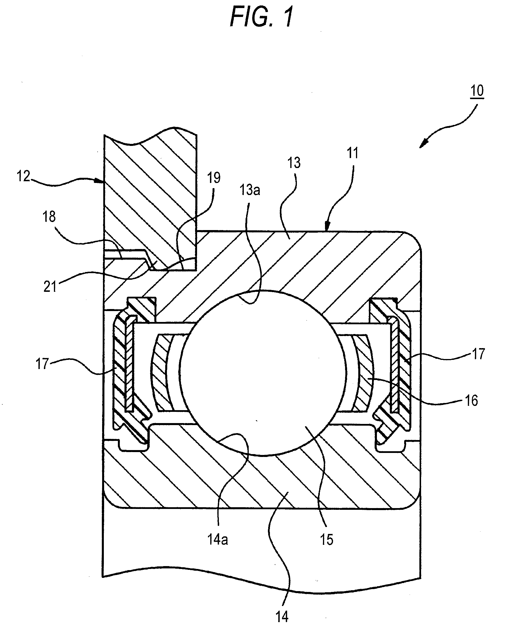
[0038]FIG. 1 is a sectional view showing a main portion for explaining an embodiment of the bearing unit of the present invention. FIG. 2 is a perspective view showing a state in which a retainer plate is engaged and fixed onto an outer circumferential face of a small diameter step portion of an outer ring. FIG. 3 is a perspective view taken from the back side of FIG. 2. FIG. 4 is a sectional view of a main portion for explaining a step in which an engagement pawl is formed in an inner circumferential portion of a retainer plate. FIG. 5 is a sectional view of a main portion for explaining a step in which a retainer plate is engaged with a small diameter step portion of an outer ring. FIG. 6 is a sectional view of a main portion for explaining a state in which an engagement pawl of a retainer plate is engaged with an engagement groove of an outer ring.

[0039]As shown in FIG. 1, the bearing unit 10 of th...

second embodiment

[0052]Referring to FIGS. 7 and 8, the second embodiment of the present invention will be explained in detail below.

[0053]FIG. 7 is a sectional view of a main portion for explaining an embodiment of a bearing unit of the present invention. FIG. 8 is a schematic illustration for explaining a step in which an outer ring of a rolling bearing and a retainer plate are combined with each other.

[0054]Different points of the second embodiment from the first embodiment are the forming method of engagement pawls 121 and the fixing method of the retainer plate 12 and the rolling bearing 11 in which the engagement pawls 121 are used. Except for the above points, the constitution of the rolling bearing 11 and the retainer plate 12 of the second embodiment is substantially the same as that of the first embodiment. Like reference marks are used to indicate like members in the first and the second embodiment and the detailed explanations are omitted here.

[0055]Referring to FIG. 8, an assembling meth...

third embodiment

[0060]Referring to FIGS. 9, 10 and 11, the third embodiment of the present invention will be explained in detail below.

[0061]FIG. 9 is a sectional view of a main portion for explaining an embodiment of a bearing unit of the present invention. FIG. 10 is a schematic illustration for explaining a step in which a protruding portion is formed on a retainer plate. FIG. 11 is a schematic illustration for explaining a step in which an outer ring of a rolling bearing and a retainer plate are combined with each other.

[0062]Different points of the third embodiment from the first and the second embodiment are the forming method of the engagement pawls 221 and the fixing method of the retainer plate and the rolling bearing 11 in which the engagement pawls 221 are used. Except for the above points, the constitution of the rolling bearing 11 and the retainer plate 12 of the third embodiment is substantially the same as that of the first and the second embodiment. Like reference marks are used to ...


PUM

PropertyMeasurementUnit
diameteraaaaaaaaaa
sizeaaaaaaaaaa
dimensionsaaaaaaaaaa

Abstract

There is provided an assembling method of a bearing unit which has a bearing having an outer ring and a retainer plate having a retainer hole for holding the outer ring. The assembling method has pressing a plurality of portions in a circumferential direction of a circumferential edge of an inner circumferential portion of the retainer hole of the retainer plate in an axial direction so as to form engagement pawls and moving the engagement pawls of the retainer plate from one axial end of the outer ring to a engagement groove formed on an outer circumferential surface of the outer ring so as to engage the engagement pawls of the retainer plate with the engagement groove of outer ring.

Description

BACKGROUND OF THE INVENTION[0001]1. Field of the Invention[0002]The present invention relates to a bearing unit used for a rotation supporting portion of, for example, a gear incorporated into a transmission. The present invention also relates to an assembling method of the bearing unit.[0003]2. Description of the Related Art[0004]As for this type bearing unit, as shown in FIG. 12, there is known a bearing unit includes a rolling bearing 4 having a plurality of rolling elements 3 disposed between an inner ring 1 and an outer ring 2 as shown in FIG. 12, and a retainer plate 5 which contacts with an axial end face of the outer ring 2 of the rolling bearing 4 to fix the rolling bearing 4 to a housing H. (For example, see Japanese Patent Unexamined Publication No. JP-A-2004-028123.)[0005]It is demanded to downsize automobiles and at the same time it is demanded to downsize transmissions. In order to meet these demands, there is provided a structure shown in FIG. 13 in which a small diam...

Claims


Application Information

Patent Timeline
Patent Type & Authority Applications(United States)
IPC IPC(8): B21D53/10
CPCF16C33/586F16C35/045F16C35/067F16C2226/52F16C2226/74F16C2220/40Y10T29/49934Y10T29/49908Y10T29/49915Y10T29/49938Y10T29/49696Y10T29/49689Y10T29/49643F16C19/06F16C2226/50F16C2361/61F16C2226/60
Inventor KATOUGI, TAKAOSUGIMAN, TOMOHARU
Owner NSK LTD
Why Eureka
Try Eureka