
Device and method for repairing pipe

a technology for repairing devices and pipes, applied in shaft linings, shaft equipment, mechanical equipment, etc., can solve problems such as difficulty in obtaining adhesive bonds between liner tubes, damage to the junction between lateral pipe lines and main pipe lines, and interior of the pipe being repaired is often greasy or oily, so as to achieve effective sealing against entry of ground water

Active Publication Date: 2009-03-05
LMK TECH LLC
View PDF26 Cites 66 Cited by
  • Summary
  • Abstract
  • Description
  • Claims
  • Application Information

AI Technical Summary

Benefits of technology

[0015]According to another feature of the present invention, a hydrophilic band or band made of a similar impermeable compressible material is positioned on the main liner portion of a main / lateral liner. The band surrounds the opening between the main and lateral liners and is disposed between the main pipe line and the liner around the periphery of the opening between the main and lateral pipes to effectively seal against entry of ground water at the pipe junction. Again, this apparatus is suitable for use in both inversion-style applications and pull-in-place applications.

Problems solved by technology

Often damage occurs at the junction between the lateral pipe line and the main pipe line.
However, considerable difficulty has been encountered in attempting to obtain an adhesive bond between the liner tube and the interior of the pipe being repaired.
The interior of the pipe being repaired is often greasy or oily even after high pressure water jetting is performed.
Attempts have been made to wash the interior of the pipe line with some success, but washing the interior of the pipe line is often only partial and not reliable.
Furthermore, in some types of pipes, such as polyethylene pipes, an adhesive bond cannot be maintained between the resin impregnated liner tube and the polyethylene pipe even if the pipe is free from grease and oils.
Even in those instances where the interior of the pipe line is suitable for accepting a liner, shrinkage of the liner can occur, which creates a gap that allows ground water to flow around the liner and eventually infiltrate the pipe line.
These thermoset resins tend to shrink during the curing process, thus creating a gap between the liner and the pipe.
Even the slightest shrinkage in the liner can be problematic.

Method used


Image

  • Device and method for repairing pipe
  • Device and method for repairing pipe
  • Device and method for repairing pipe

Examples


Embodiment Construction

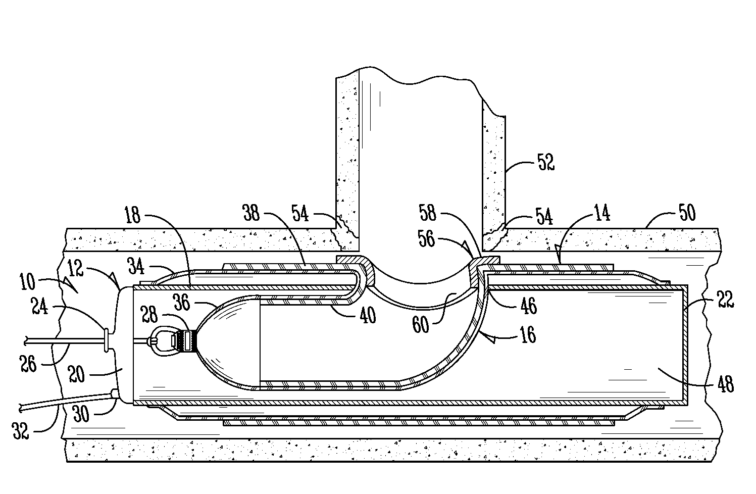
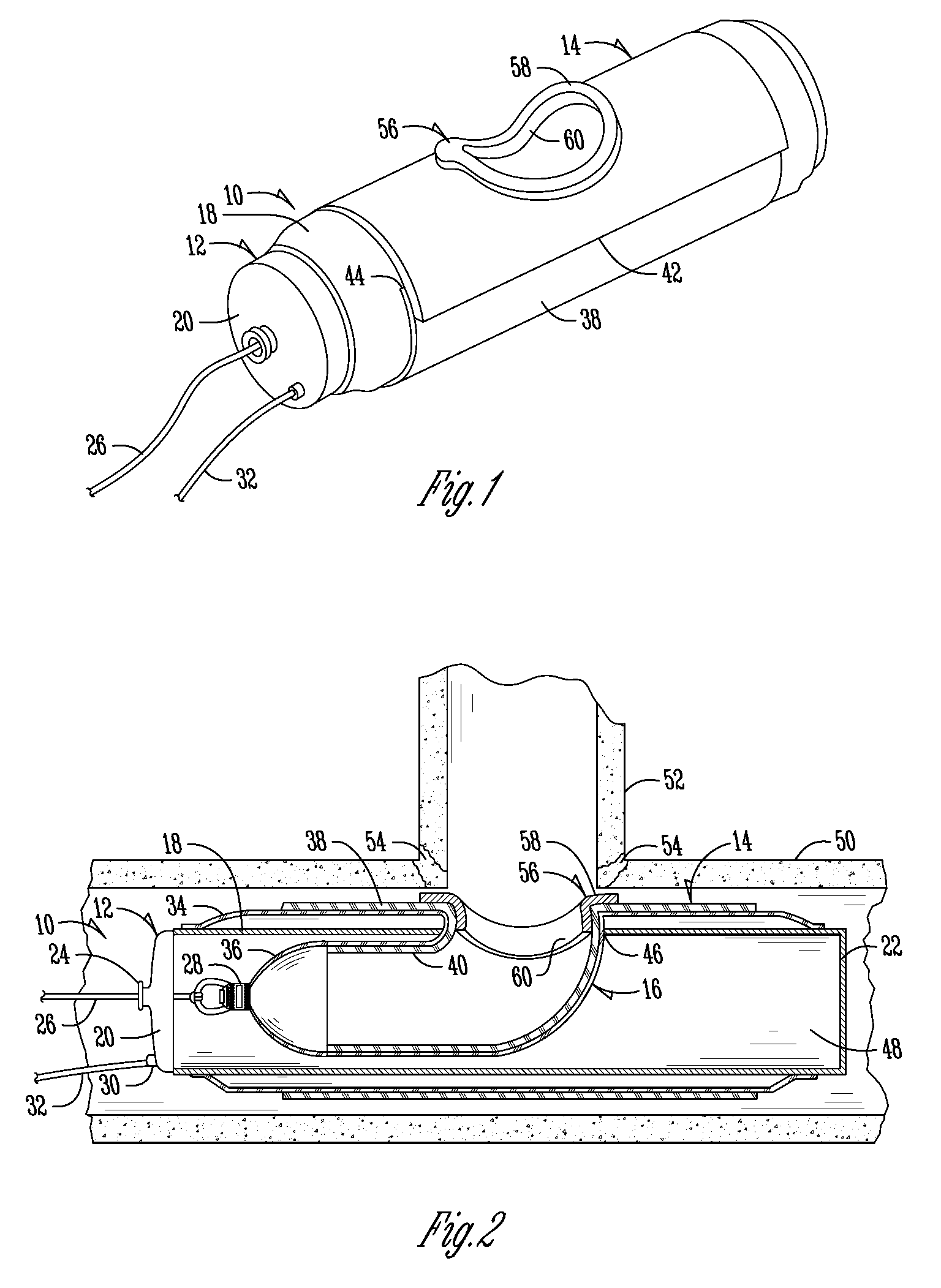
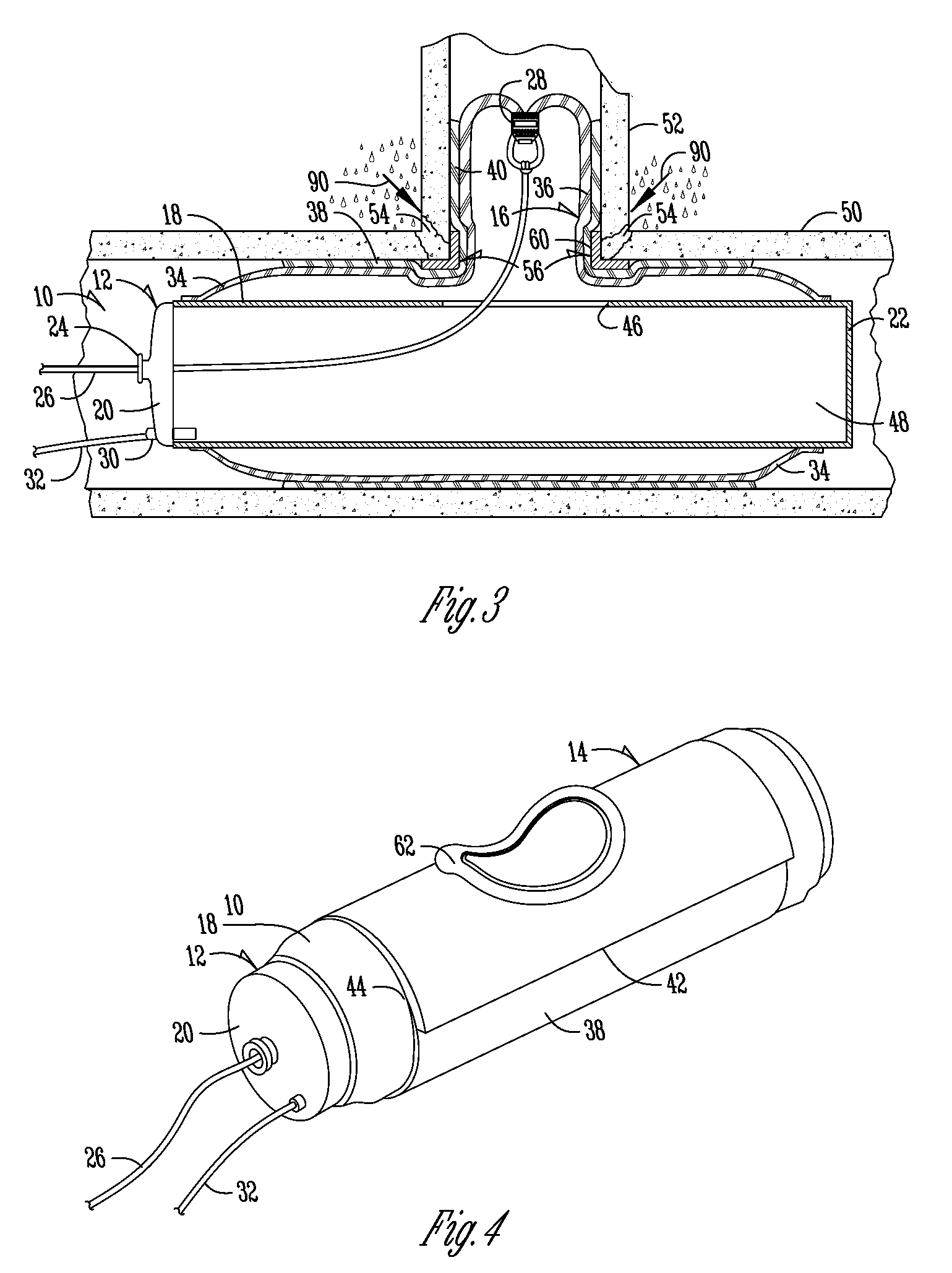
[0026]Referring to FIGS. 1-3, a repair assembly is generally designated by the numeral 10. Repair assembly 10 includes a launcher device 12 having mounted thereto a T-shaped or Y-shaped liner assembly 14. Repair assembly 10 also houses a T-shaped or Y-shaped bladder assembly 16. In the particular configuration shown in FIGS. 1-3, the liner assembly 14 and bladder assembly 16 are T-shaped, but they can also be Y-shaped to accommodate a lateral pipe line that intersects with a main pipe line at an oblique angle.

[0027]Launcher device 12 includes side walls 18, an end cap 20 and an end wall 22, all of which form a launcher device cavity 48. End cap 20 includes a line inlet 24 through which a line 26 extends. Line 26 is attached to a closed bladder tube end 28. Also extending through end cap 20 is an air inlet 30 which is connected to an air hose 32. T-shaped or Y-shaped bladder tube assembly 16 includes a main bladder tube 34 and a lateral bladder tube 36. Similarly, the T-shaped or Y-s...


PUM


Abstract

A liner tube is provided for repairing either a single pipe line or a main pipe line having a lateral pipe line connected thereto. The liner tube assembly includes a liner tube impregnated with a liquid material capable of curing and hardening. The liner tube includes a gasket or band positioned about the juncture of the pipe lines. The gasket or bands form a tight seal between the liner tube and the pipe line.

Description

BACKGROUND OF THE INVENTION[0001]The present invention relates to a device and method for repairing pipe, such as underground sewer pipe and the like.[0002]Prior methods for repairing damaged pipe lines include moving a liner tube impregnated with a liquid material capable of curing and hardening to the position within the pipe where the damaged portion is located. The liner tube is urged in an outward radial direction into contact with the pipe line being repaired and the liquid material impregnating the liner tube is permitted to cure and harden. The liner tube forms an interior liner in the pipe for the pipe line being repaired.[0003]On some occasions lateral pipe lines are connected to main pipe lines. Often damage occurs at the junction between the lateral pipe line and the main pipe line. T-shaped or Y-shaped liner tubes have been utilized to fit within the junction between the lateral pipe line and the main pipe line. Liner tubes form a T-shaped or Y-shaped liner after harden...

Claims


Application Information

Patent Timeline
IPC IPC(8): F16L55/16
CPCF16L55/1651F16L55/18F16L55/179F16L55/1656F16L55/265
Inventor KIEST, JR., LARRY W.
Owner LMK TECH LLC
Learn More