Disk brake apparatus
a technology of brake apparatus and disk, which is applied in the direction of brake cooling, brake system, brake, etc., can solve the problems of affecting the operation of the brake, and generating rattle, so as to achieve the effect of effectively preventing the occurrence of judder
- Summary
- Abstract
- Description
- Claims
- Application Information
AI Technical Summary
Benefits of technology
Problems solved by technology
Method used
Image

Examples
first embodiment
[0023]Hereinafter, a disk brake apparatus of a first embodiment of the present invention will be described with reference to FIGS. 1 to 3.
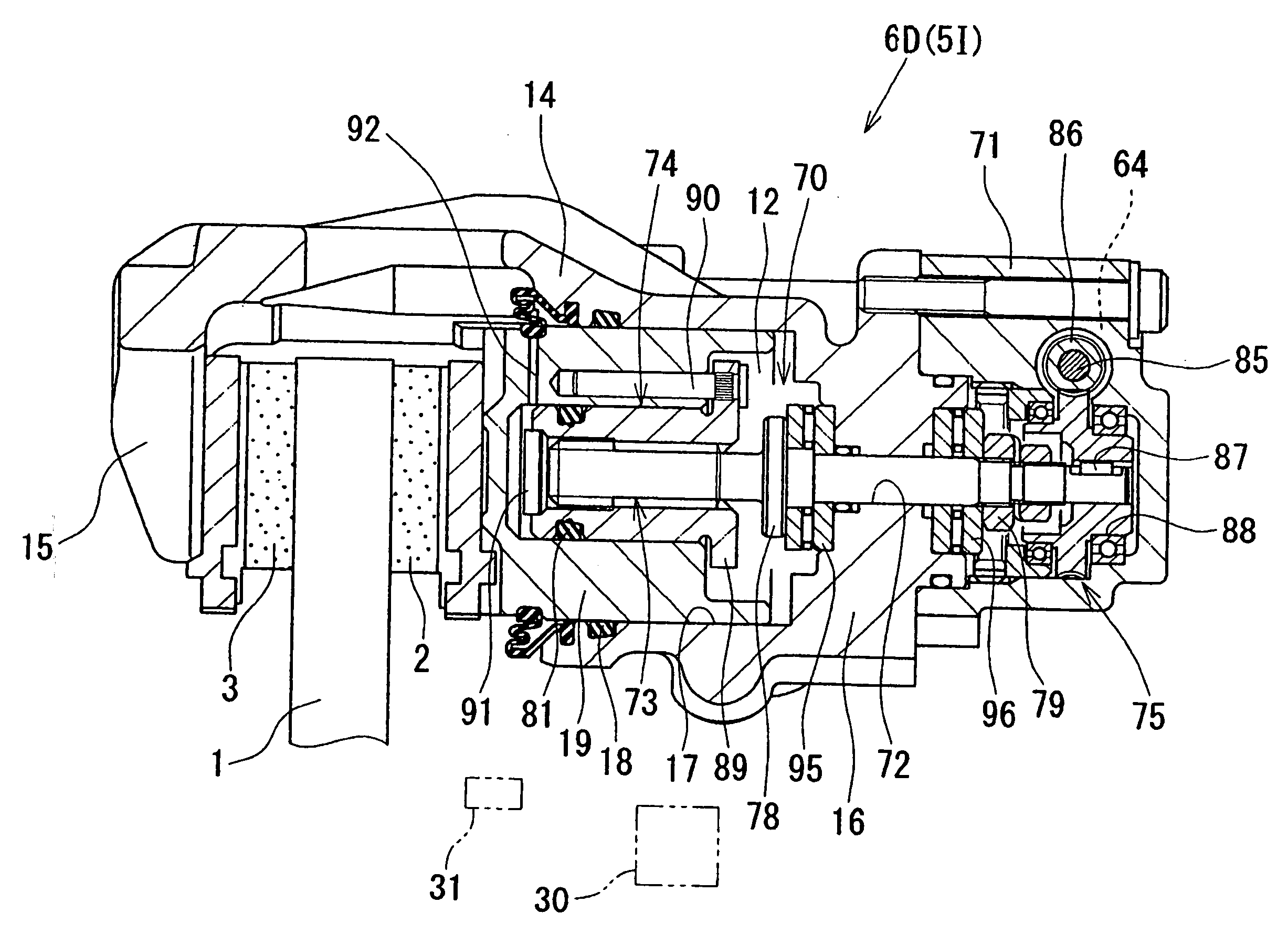
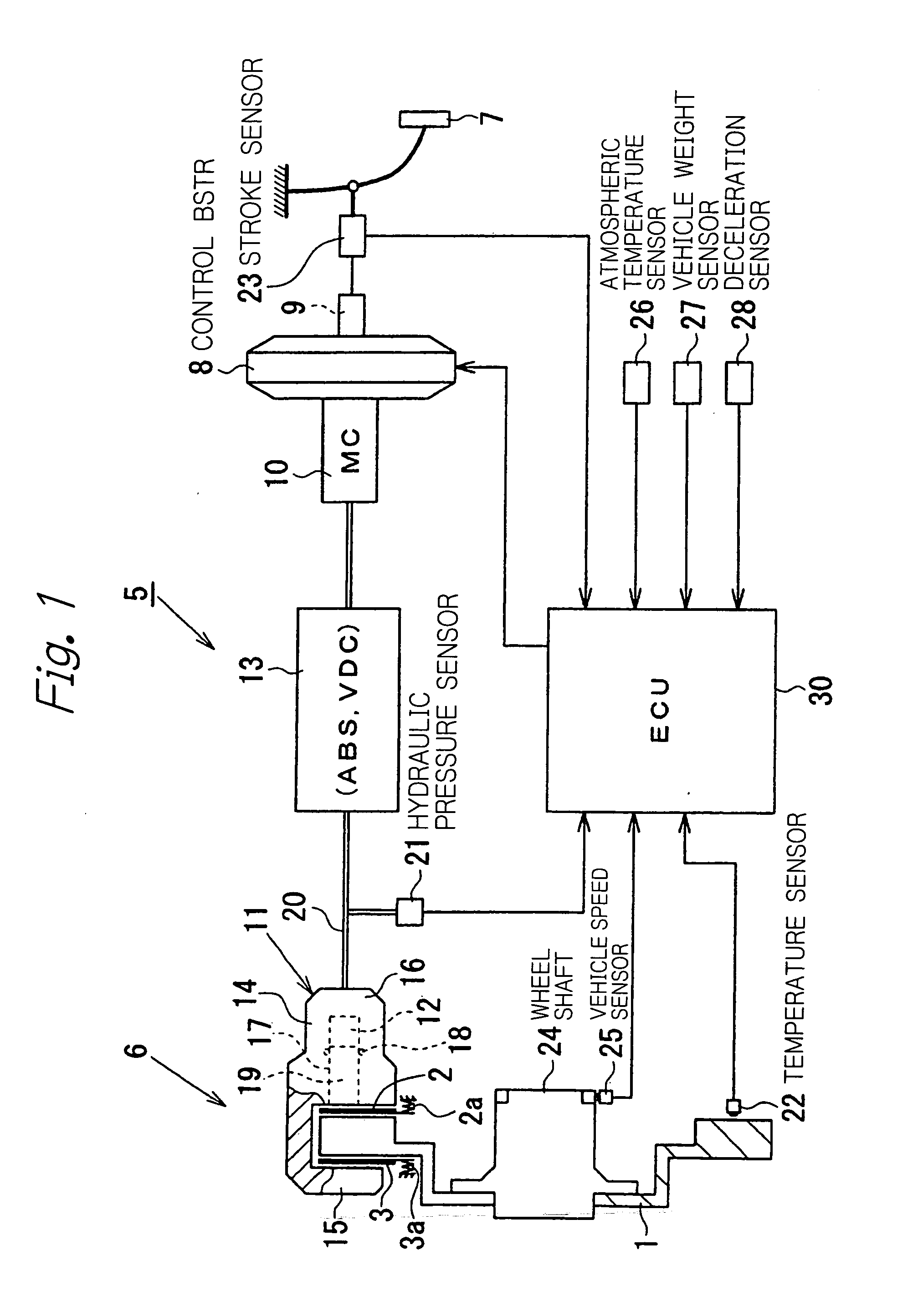
[0024]As shown in FIG. 1, a disk brake apparatus 5 generally comprises a floating caliper type disk brake 6, an ACC control booster (Adaptive Cruise Control control booster) 8, a master cylinder (hereinafter referred to as “MC”) 10, and an automatic brake system 13. The ACC control booster 8 is adapted to amplify a force of pressing of a brake pedal 7 and output the amplified force, or is adapted to generate an output using a solenoid 9 (actuator), independently of the force of pressing of the brake pedal 7. The MC 10 is adapted to generate a hydraulic pressure according to the amplified output of the force of pressing of the brake pedal 7, or by the output that the ACC control booster 8 generates using the solenoid 9 (actuator). An ABS (Anti-lock Brake System) and a VDC (Vehicle Dynamics Control System) are incorporated in the automatic brake sys...
second embodiment
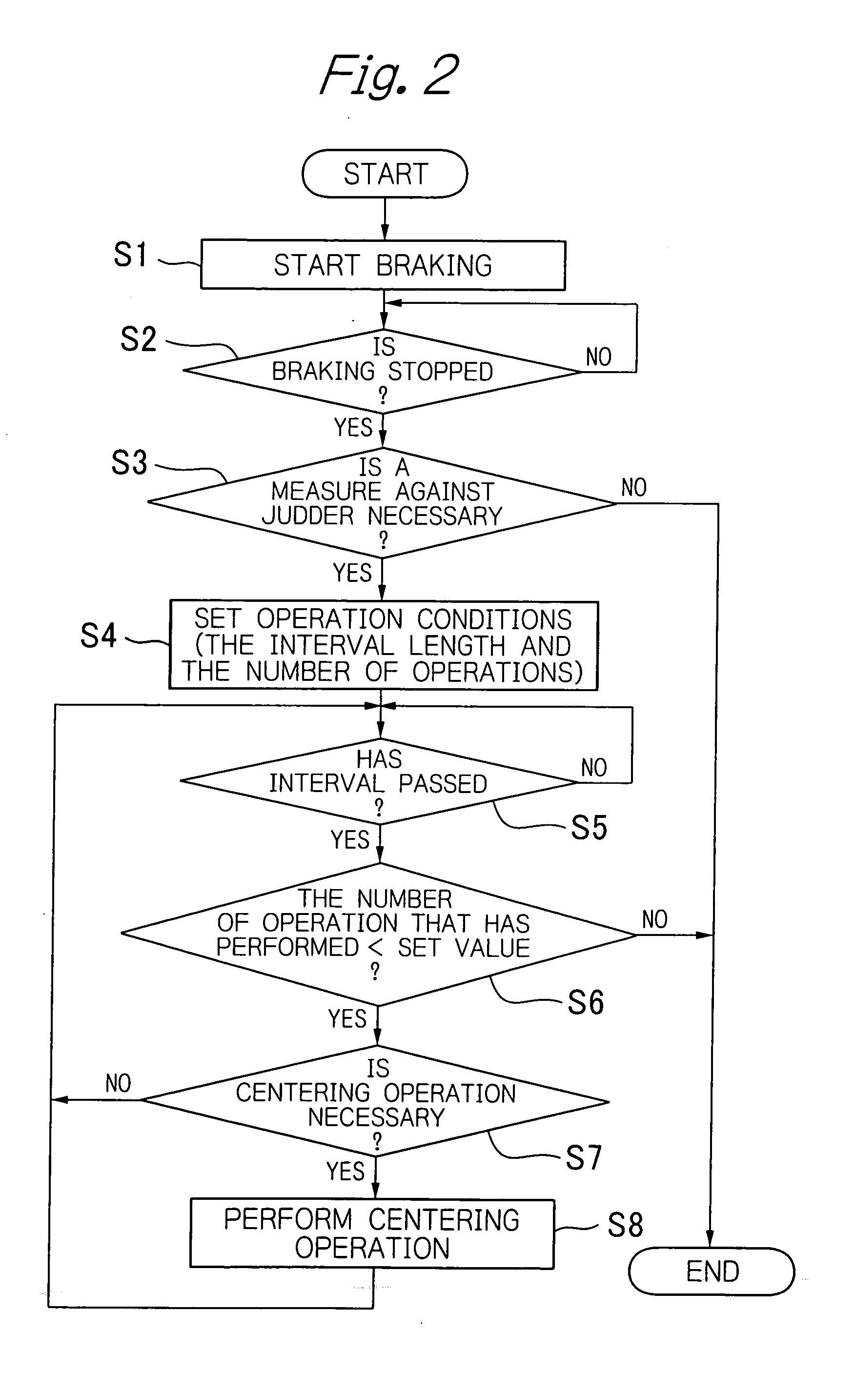
[0046]In the first embodiment, it is determined at step S3 whether the centering operation (clearance adjusting control) should be performed, based on the detection value of the temperature sensor 22. However, the temperature sensor 22 may be replaced with pad displacement sensors 31a and 31b or a rotor displacement sensor 31c operable to detect displacement of the disk rotor 1 (see FIG. 4, thermal deformation measuring unit), and it may be determined whether the centering operation (clearance adjusting control) should be performed based on an amount of deformation of the disk rotor 1 obtained from a detection signal of the pad displacement sensors 31a and 31b or the rotor displacement sensor 31c.
[0047]FIG. 4 schematically illustrates a disk brake apparatus of a second embodiment of the present invention. A disk brake apparatus 5A of the second embodiment will be described referring to FIGS. 4 and 5, also sometimes referring to FIGS. 1 to 3 as necessary. The second embodiment is pr...
third embodiment
[0064]Although in the first and second embodiments, the actuator is embodied by the ACC control booster 8 or 8A (more correctly, the solenoid 9 or 9A disposed at the ACC control booster 8 or 8A), the actuator may be embodied by other means. For example, as shown in FIG. 6, in a disk brake apparatus 5B (a third embodiment), an actuator may be embodied by a VDC pump 32 (hydraulic pump) disposed at a VDC (Vehicle Dynamics Control system) incorporated in an automatic brake system 13. The disk brake apparatus 5B of the third embodiment comprises a booster (boosting apparatus) 8B that does not execute the ACC control, instead of the ACC control boosters 8 and 8A. The third embodiment comprises a rotor displacement sensor 31c, similarly to the second embodiment, and a thermal gradient amount (displacement) of a disk rotor 1 is calculated using a detection signal of the sensor 31c to determine whether the centering operation (clearance adjusting control) should be performed.
[0065]In the thi...
PUM
 Abstract
Description
Claims
Application Information