
Display device

a technology for displaying devices and displaying devices, which is applied in the direction of static indicating devices, instruments, transportation and packaging, etc., can solve the problems of limited viewing angle of display devices and uncomfortable sensations for passengers sitting in rear center seats, and achieve enhanced image quality of assistant driver's seat, eliminating crosstalk, and enhancing the effect of image quality

Inactive Publication Date: 2009-03-05
FUJITSU GENERAL LTD
View PDF12 Cites 151 Cited by
  • Summary
  • Abstract
  • Description
  • Claims
  • Application Information

AI Technical Summary

Benefits of technology

The present invention provides a display device that can adjust the viewing angle and range of images on the screen for multiple viewing directions. This allows for proper adjustment of the image viewing direction, viewing angle, and viewing range for each viewer. Additionally, the invention addresses the issue of multiple videos and sounds being mixed in the passenger compartment, ensuring that each viewer can view and hear the intended video or sound. The invention also includes a light-blocking section to control the direction of light emerging from the display, ensuring that the viewer's perspective is not compromised. The invention can display and output different images and sounds for different viewing angles and directions, making it easy to utilize the available space and provide information to the occupants of the vehicle.

Problems solved by technology

Because of its structure, every display device has a limited viewing angle within which the display is viewable.
However, as the position of the viewer of the display device is not fixed, an adjustment must be made to match the position of the viewer.
This can give an uncomfortable sensation to the passenger sitting in the rear center seat.

Method used


Image

  • Display device
  • Display device
  • Display device

Examples


Embodiment Construction

[0183]Various embodiments of the present invention will be described below with reference to the drawings. In each embodiment, parts corresponding to those already described in the preceding embodiment(s) are designated by the same reference numerals, and a description already given may not be repeated. It is to be understood that when only a portion of a given configuration is described, the remaining portion of the configuration is the same as the corresponding portion described in the preceding embodiment(s). It should also be noted that, besides the combinations of parts specifically described in the embodiments given herein, it is also possible to partially combine different embodiments as long as the resulting combination does not present any particular problem.

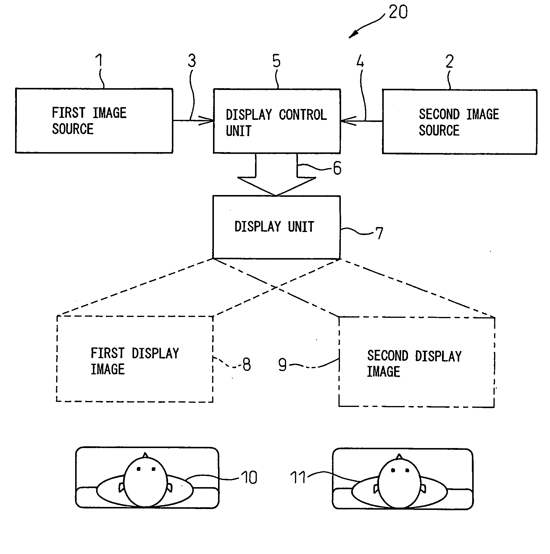
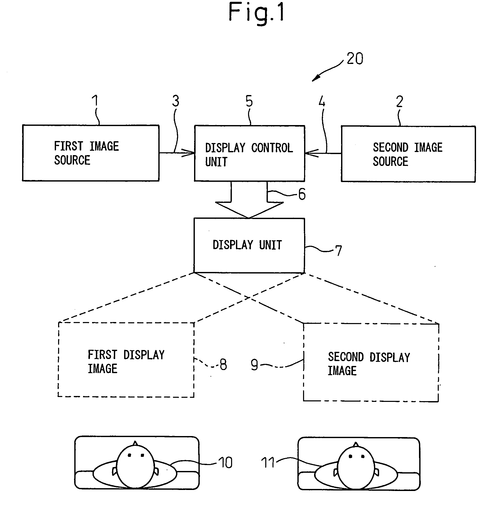
[0184]FIG. 1 is a diagram schematically illustrating a display device 20 according to the present invention.

[0185]The display device 20 (referred to “multiple view display device”) has a display control unit 5 (control ...


PUM


Abstract

The invention provides a display device wherein provisions are made to be able to properly adjust the image viewing direction, viewing angle, or viewing range on the display device. The display device includes a display section capable of displaying independent images intended for a plurality of different viewing directions on the same screen, an information acquiring section for acquiring orientation information concerning the orientation of the images, and an image direction varying section for varying the orientation of the images based on the orientation information acquired by the information acquiring section.

Description

FIELD OF THE INVENTION[0001]The present invention relates to a display device that can, in effect, simultaneously display different independent information on the same screen for viewing by different individual users.BACKGROUND OF THE INVENTION[0002]It is known to provide a display device that displays different images on the same display panel for viewing from different directions, for example, from two different directions (refer, for example, to patent documents 1 and 2). Specifically, there is disclosed a display device that can display two different screens simultaneously on the same liquid crystal display (LCD), allowing, for example, in a vehicle, the driver and the passenger to view the different screens from their respective positions (refer, for example, to patent documents 3 and 4). There is also disclosed a dual screen display device that can simultaneously display two different images on the same screen (refer, for example, to patent documents 5 and 6). Such display dev...

Claims


Application Information

Patent Timeline
Patent Type & Authority Applications(United States)
IPC IPC(8): G09G3/22
CPCB60K35/00B60K2350/901B60K2350/903G09G2320/068G02F1/133G09G3/003G09G5/00G02F1/1323B60K35/656B60K35/654B60K35/21B60K35/60B60K35/10B60K35/53B60K35/29B60K35/22B60K35/81B60K35/90B60K35/265B60K35/285B60R11/02
Inventor FUKUDA, YASUHIROKAMOTO, MITSUHIROFUJIMOTO, HIROYUKIHASHIMOTO, YOSHIYUKIYOKAWA, TAKUUETA, YOSHIKAZUYOSHIMOTO, TAKUMISAITO, TOMOKIKATO, TAKASHI
Owner FUJITSU GENERAL LTD
Learn More