Liquid crystal display device

a liquid crystal display and display screen technology, applied in non-linear optics, instruments, optics, etc., can solve the problems of increasing increasing the thickness of the optical compensation sheet, and the arrangement of the newly introduced optical compensation film is disadvantageous not only in terms of cost but also in terms of downsizing the thickness of the liquid crystal display device, so as to increase the complexity of the structure and the cost, and improve the viewing angle.

Inactive Publication Date: 2009-03-05
TRIVALE TECH
View PDF7 Cites 25 Cited by
  • Summary
  • Abstract
  • Description
  • Claims
  • Application Information

AI Technical Summary

Benefits of technology

[0013]As stated in Patent document 4, it can be seen that the placement of the optical compensation film having a compound containing discotic structure units is desired to further improve the viewing angle. However, it has increased the complexity of the structure and the cost owing to the arrangement of the newly introduced optical compensation film.
[0015]In one aspect, the present invention has been made in view of above-mentioned problems, and one of the objects of the present invention is to provide a transverse electric field mode liquid crystal display device capable of improving the viewing angle characteristic in black display at an oblique viewing angle by a simple structure.
[0021]In accordance with one aspect, the present invention has an advantageous effect that it can provides a transverse electric field mode liquid crystal display device having an excellent viewing angle characteristic in black display at an oblique viewing angle attained by a simple structure.

Problems solved by technology

However, it has increased the complexity of the structure and the cost owing to the arrangement of the newly introduced optical compensation film.
The arrangement of the newly introduced optical compensation film is disadvantageous not only in terms of the cost but also in terms of downsizing in the thickness of a liquid crystal display device.
In particular, in the case where the optical compensation is achieved by using several stretched films each composed of a birefringent polymer, it not only increases the thickness of the optical compensation sheet, but also raises a new problem that the peeling and warping occur between the films by the shrinking, caused by changes in temperature and humidity, of the adhesion layer that is used to stack the stretched films.
In addition, it also poses another problem that the stretched birefringent polymer film is generally expensive, and thereby further increases the cost.

Method used


Image

  • Liquid crystal display device
  • Liquid crystal display device
  • Liquid crystal display device

Examples


example

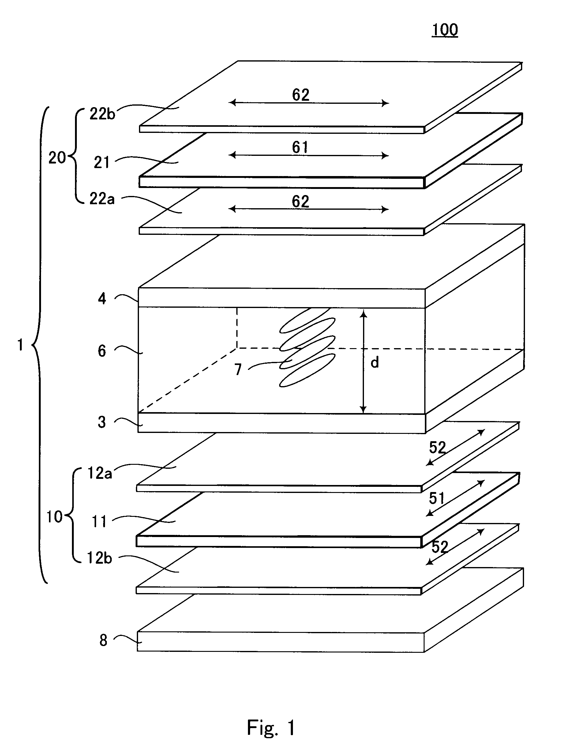
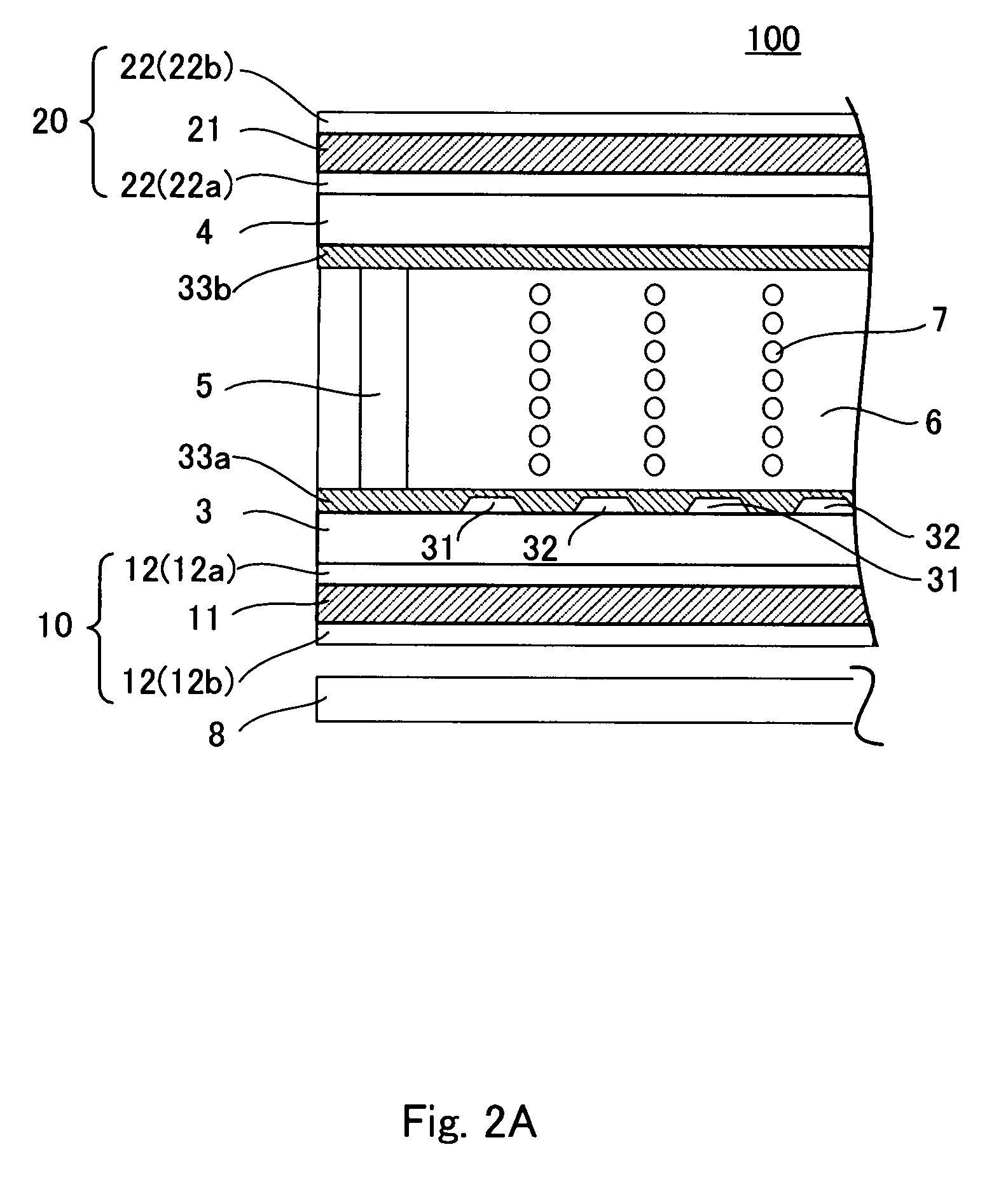
[0057]Next, the present invention is explained in more specific manner with a more example hereinafter. However, the scope of the present invention is not limited to the example explained below. A liquid crystal display device 100 in accordance with this example, by way of illustration, adopts IPS mode as shown in FIG. 2, and uses p-type liquid crystal. A liquid crystal display panel 1 was manufactured in the following manner.

[0058]A liquid crystal layer having following characteristics was used as the liquid crystal layer 6.[0059]refractive index anisotropy: Δn=0.089 (550 nm, 20° C.)[0060]dielectric constant anisotropy: Δε=+7.8[0061]thickness of liquid crystal layer 6: d=3.6 μm[0062]retardation of liquid crystal layer 6: Δn−d=320 nm

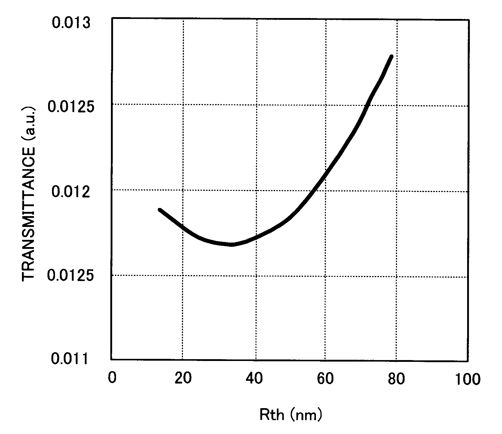
[0063]The in-plane retardations Re of the transparent protective films 12 (12a, 12b), 22 (22a, 22b) were equal to or less than 10 nm. Furthermore, the directions of the delay phase axes 52 and 62 of the in-plane retardations Re of the first and second tr...


PUM

PropertyMeasurementUnit
thicknessaaaaaaaaaa
thicknessaaaaaaaaaa
thicknessaaaaaaaaaa

Abstract

A transverse electric field mode liquid crystal display device capable of improving the viewing angle characteristic in black display at an oblique viewing angle with a simple structure is provided. In the liquid crystal display device in accordance with one aspect of the present invention, (a) the product (ΔA·d) of the thickness d of the liquid crystal layer sandwiched between a pair of substrates and the refractive index anisotropy Δn of the liquid crystal layer is within the range of 320 nm±20 nm, (b) each of the pair of polarizing plates is composed of a polarizer and transparent protective films sandwiching the polarizer therebetween, and the polarizing plate and the substrate are directly stuck together without any retardation film or optical compensation layer interposed therebetween, (c) the delay phase axis of the transparent protective film that protects the liquid crystal layer side is generally parallel with the absorption axis of the polarizer in each of the pair of polarizing plates, and (d) the in-plane retardation Re is equal to or less than 10 nm, and the retardation in thickness direction Rth is no less than 30 nm and no greater than 40 nm for the transparent protective film that protects the liquid crystal layer side in each of the pair of polarizing plates.

Description

BACKGROUND OF THE INVENTION[0001]1. Field of the Invention[0002]The present invention relates to a transverse electric field mode liquid crystal display device. In particular, the present invention relates to improvements in the display of black color at an oblique viewing angle.[0003]2. Description of the Related Art[0004]In a liquid crystal display panel, the light transmittance is adjusted by applying voltage to the liquid crystal to control the alignment of the liquid crystal. Liquid crystal display modes are classified according to their types of the alignment changes of liquid crystal. Currently, major modes include TN (Twisted Nematic) mode, VA (Vertical Alignment) mode, and IPS (In-Plane Switching) mode.[0005]In the TN mode, a longitudinal electric field is vertically applied to the substrate to make the liquid crystal molecules stand up or lie down with respect to the substrate surface in response to the applied voltage, in order to change the display state. In the VA mode,...

Claims


Application Information

Patent Timeline
Patent Type & Authority Applications(United States)
IPC IPC(8): G02F1/1335
CPCG02F1/133634G02F2001/133635G02F1/134363G02F1/133635
Inventor ISHIKAWA, YOSHIMITSUKURATA, TETSUYUKI
Owner TRIVALE TECH
Why Eureka
Try Eureka