Bone Plate System

a technology of bone plate and plate plate, applied in the field of bone plate system, can solve the problems of affecting the recovery, grafting, fusion process, and causing harm to the spine, and achieve the effect of improving torsional stability

Inactive Publication Date: 2009-03-05
PIONEER SURGICAL TECH INC
View PDF102 Cites 76 Cited by
  • Summary
  • Abstract
  • Description
  • Claims
  • Application Information

AI Technical Summary

Benefits of technology

[0011]In accordance with the present invention, several embodiments of bone plate systems as well as tools and methods for installing the same are provided. The present bone plate systems overcome shortcomings of prior bone plate systems and generally allow motion for the bone anchors such that they may move relative to the bone plates to accommodate shifting or settling of secured vertebrae while offering desirable levels of control and predictability of this motion. Furthermore, one exemplary embodiment featuring aspects according to the present invention represents a new and novel approach to combining a narrow bone plate profile with enhanced torsional stability.

Problems solved by technology

Thus, settling of the vertebrae and changes in spinal curvature may be accounted for, which is desirable because if pivoting alone may not account for the expected settling of a patient's vertebrae, a harmful load path may be created through the spine, hindering the recovery, grafting, and / or fusion process.

Method used


Image

  • Bone Plate System
  • Bone Plate System
  • Bone Plate System

Examples


Embodiment Construction

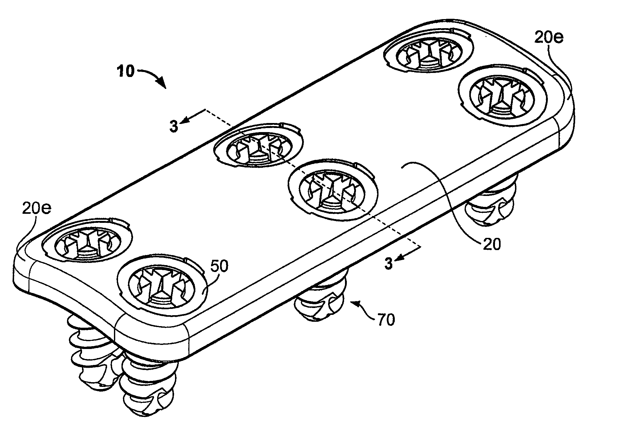
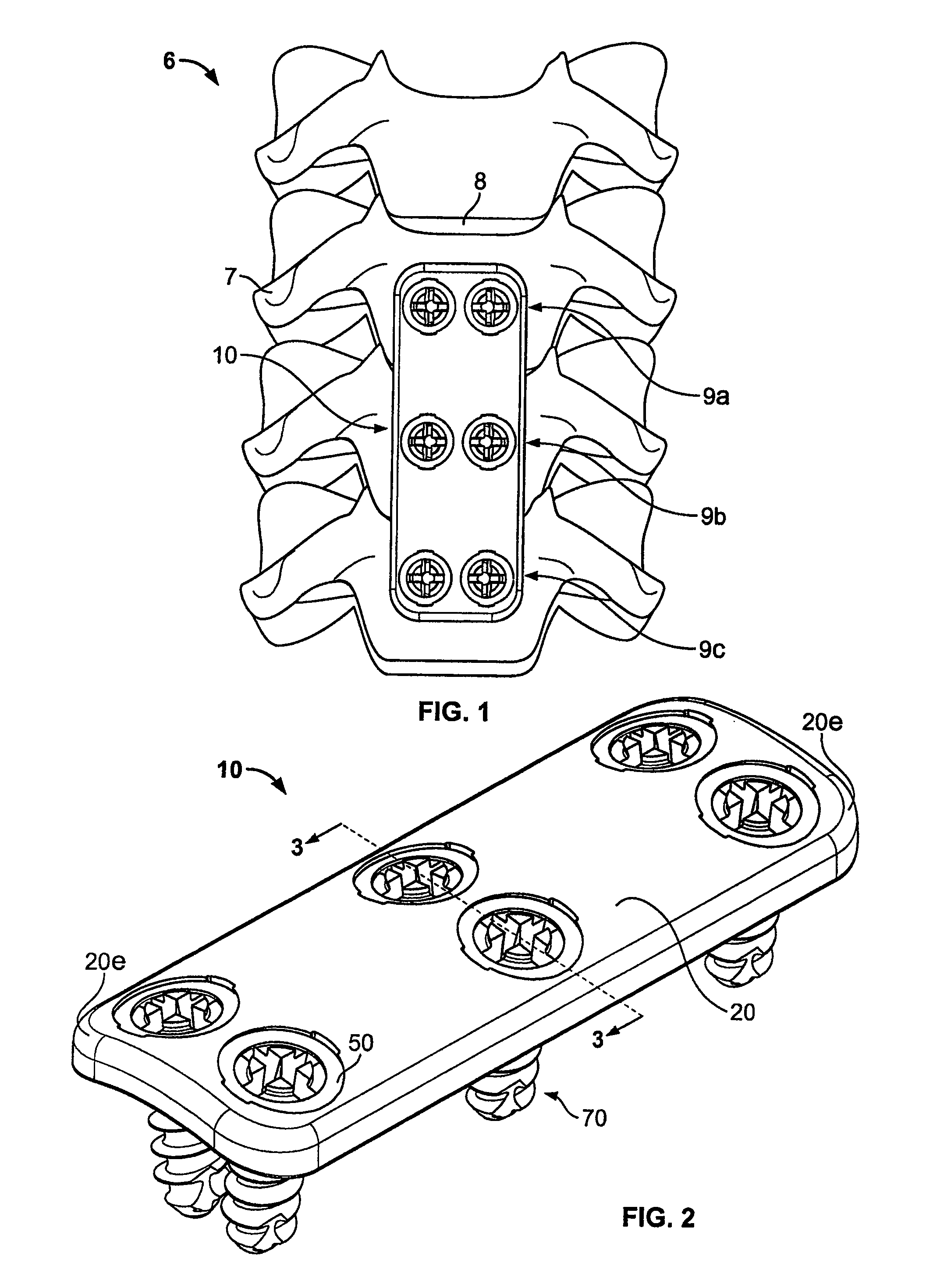
[0076]Generally speaking, pursuant to these various embodiments, bone plate systems are disclosed herein for securing a plurality of bones 7 in a desired orientation and arrangement. In some forms, the bone plate system utilizes a dynamized plate with dynamic throughbores so that bones 7 may compress and shift toward each other, such as with dynamic or dynamized bone plate systems 410, 510 shown in FIGS. 27 and 30, respectively. In other forms, bone plate systems utilize standard plate members with throughbores of the same size, such as with standard or non-dynamized bone plate systems 10, 110, 210 shown in FIGS. 2, 14, and 19, respectively. In other forms, the bone plate systems utilize monoplate or single-row or single screw per vertebral level embodiments, such as with the monoplate bone plate system 310 shown in FIG. 23.

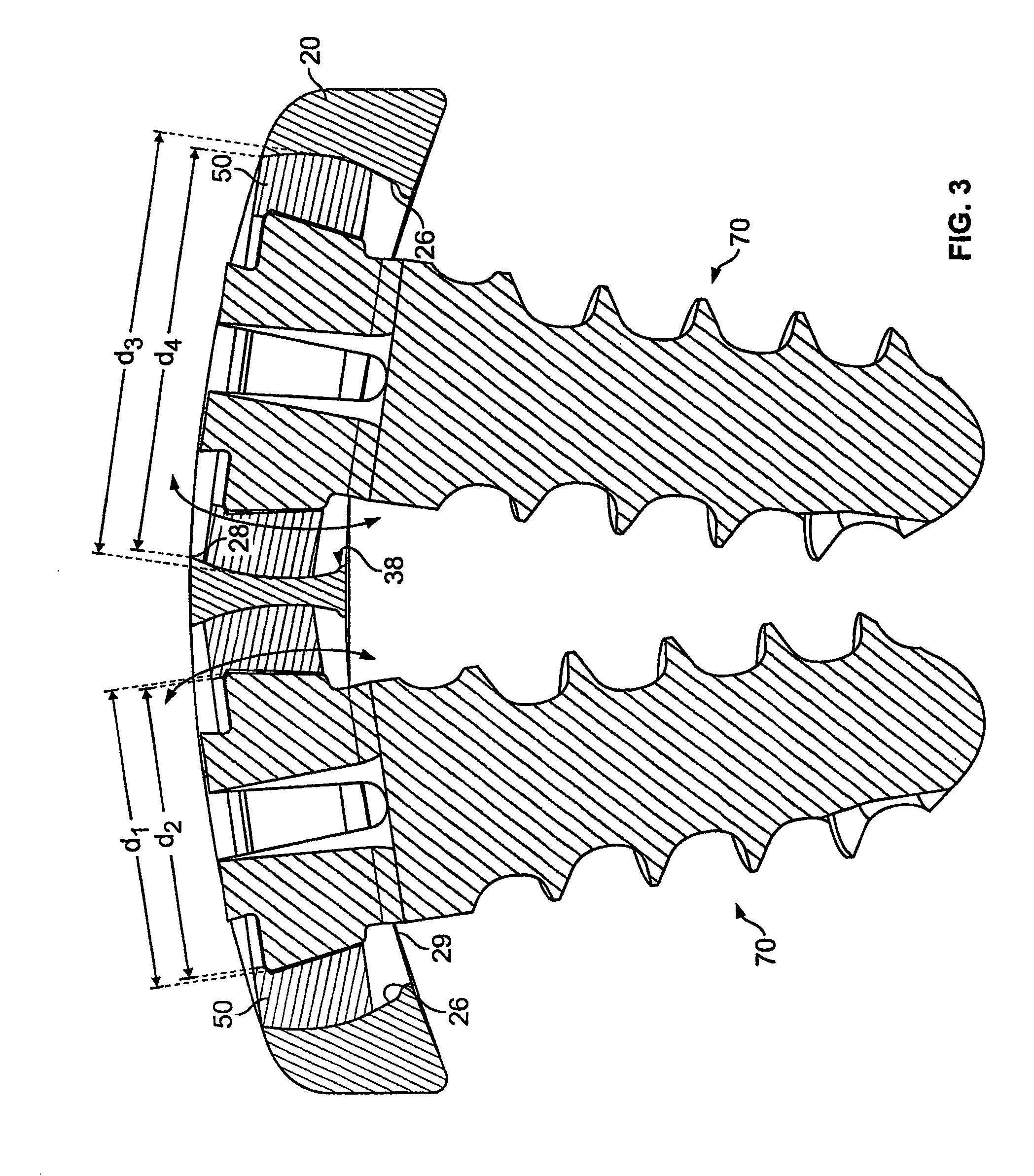
[0077]Referring to FIGS. 1-13, a standard bone plate system 10 is shown which may assist in the healing and repair of damaged, fractured, or broken bones. In the...


PUM


Abstract

Bone plate systems for surgical implants and bone repair are provided. The bone plate is multi-tiered for receiving bone anchors for securing a plurality of bones or bone fragments in a desired relationship. The plate members include throughbores for receiving a pivot base therein, with head ends of the bone anchors being secured within the pivot bases. The throughbores may permit and define a translation path for the pivot base and the bone anchor secured therein relative to the plate. The configuration of the pivot base and the throughbore facilitate pivoting and optional translation of the pivot base relative to the plate. With the bone anchor seated within the pivot base, an apparatus for inhibiting bone anchor back out is employed.

Description

CROSS-REFERENCE TO RELATED APPLICATIONS[0001]This application claims priority to United States Provisional Application Ser. No. 60 / 968,233, filed Aug. 27, 2007, and entitled “Bone Plate Systems,” which is hereby fully incorporated by reference as if set forth herein. United States Provisional Application Ser. No. 60 / 947,873, filed Jul. 3, 2007, and entitled “Bone Plate System” is also fully incorporated by reference as if set forth herein.FIELD OF THE INVENTION[0002]The invention relates to bone plate systems and, more particularly, to a bone plate system that allows for motion of the bone anchors relative to the bone plate member.BACKGROUND OF THE INVENTION[0003]There are presently many different types of plate and fixture systems for securing two or more bones or bone fragments in relative position so that the bones may fuse or heal, or so that tissue adjacent the bones may heal without disruption from the movement of the secured bones. As used herein, the term bone may refer to a...

Claims


Application Information

Patent Timeline
Patent Type & Authority Applications(United States)
IPC IPC(8): A61B17/70
CPCA61B17/7059A61B17/8004A61B17/8047A61B17/8875A61B17/8891A61B17/92A61B17/8052
Inventor PERROW, SCOTT J.FREDIN, BRAD S.FILIZETTI, CRAIGROOSE, CHRISTIAN A.
Owner PIONEER SURGICAL TECH INC
Why Eureka
Try Eureka