Bone Plate System

a technology of bone plate and esophagus, which is applied in the field of bone plate systems, can solve the problems of irritating the esophagus and other soft tissues of patients, affecting the recovery time of patients, and a relatively wide profile of the bone plate, so as to improve the torsional stability

Active Publication Date: 2009-01-08
PIONEER SURGICAL TECH INC
View PDF106 Cites 134 Cited by
  • Summary
  • Abstract
  • Description
  • Claims
  • Application Information

AI Technical Summary

Benefits of technology

[0012]In accordance with the present invention, several embodiments of bone plate systems as well as tools, instruments, and methods for installing the same are provided. The present bone plate systems overcome shortcomings of prior bone plate systems and generally allow motion for the bone anchors such that they may move relative to the bone plates to accommodate shifting or settling of secured vertebrae while offering desirable levels of control and predictability of this motion. The present invention further includes a new and novel approach to combining a narrow bone plate profile with enhanced torsional stability.

Problems solved by technology

In either case, bone plates with relatively wide profiles or a wide portion in addition to a narrow portion have a tendency to encroach upon and / or irritate the esophagus and other soft tissues of the patient during the recovery period.
Furthermore, plate members with relatively wide profiles may require a larger incision and path of entry into the body than bone plate systems with smaller profiles, causing the patient extra pain and discomfort and a resulting in a longer recovery time.
In addition, many of these systems require two bone anchors to be inserted into a least one vertebra, requiring a larger amount of time for bone plate installation and increasing the risk of degrading the structural integrity of the vertebra.
This method has clear drawbacks because the bone-engaging spikes may scratch or indent the bone, causing damage to the osseous tissue.
It is also easily foreseen that if this resistance is overcome, the surface of a bone with which the bone plate is engaged may be scraped and / or chip due to the presence of these protrusions.
The spikes may also harm or cause swelling of the intervertebral discs.
Many previous bone plate systems do not even allow such motion, and many that do provide inadequate control over the manner in which the vertebrae settle under this compression.
These designs do not properly discipline the spine, allowing the screws to angle however the spine is inclined to shift, and thus these designs may be ineffective in keeping the spine from exhibiting curvature in the coronal plane as the vertebrae settle under the compressive loads.
Additionally, if this shifting or settling of vertebrae is improperly or inadequately accounted for, additional stress may be added to the vertebrae and an undesirable load path through the spine may be created, hindering the recovery, grafting, and / or fusion process.
However, heretofore known arrangements of standard and dynamized apertures in such plates provide less than optimal capacity for controlling the movement and / or compression between more than two tiers of secured vertebrae and / or many previously known bone plates did not provide sufficient movement to allow the spine to settle naturally as a portion of the spine is compressed during the recovery period.
Inasmuch as these prior bone plate systems allowed for some settling of the spine, this settling would cause the spine to be inclined to exhibit an altered degree of curvature, which prior dynamic bone plate systems failed to accommodate.
If the spine is not allowed to adapt to this different degree of curvature and thus reach a more stable configuration, an undesirable or improper load path through the spine may be created, hindering the recovery, grafting, and / or fusion process.
If the bone screws loosen, the bones are not properly secured and may be allowed to move relative to one another in an uncontrolled manner.
This may compromise the ability to achieve optimal bone fusion and bone alignment, and it may lead to loss of graft material and damage or loss of bone.
Furthermore, when the plate is a dynamic or dynamized plate, such that at least some screws may be permitted to move relative to the plate, these issues may be further compounded or exacerbated by a screw backing out.
Additionally, in the case of anterior cervical plates, a bone anchor backing out could hinder swallowing and cause irritation or even a puncture wound to the esophagus, which may lead to infection or even death.

Method used


Image

  • Bone Plate System
  • Bone Plate System
  • Bone Plate System

Examples


Embodiment Construction

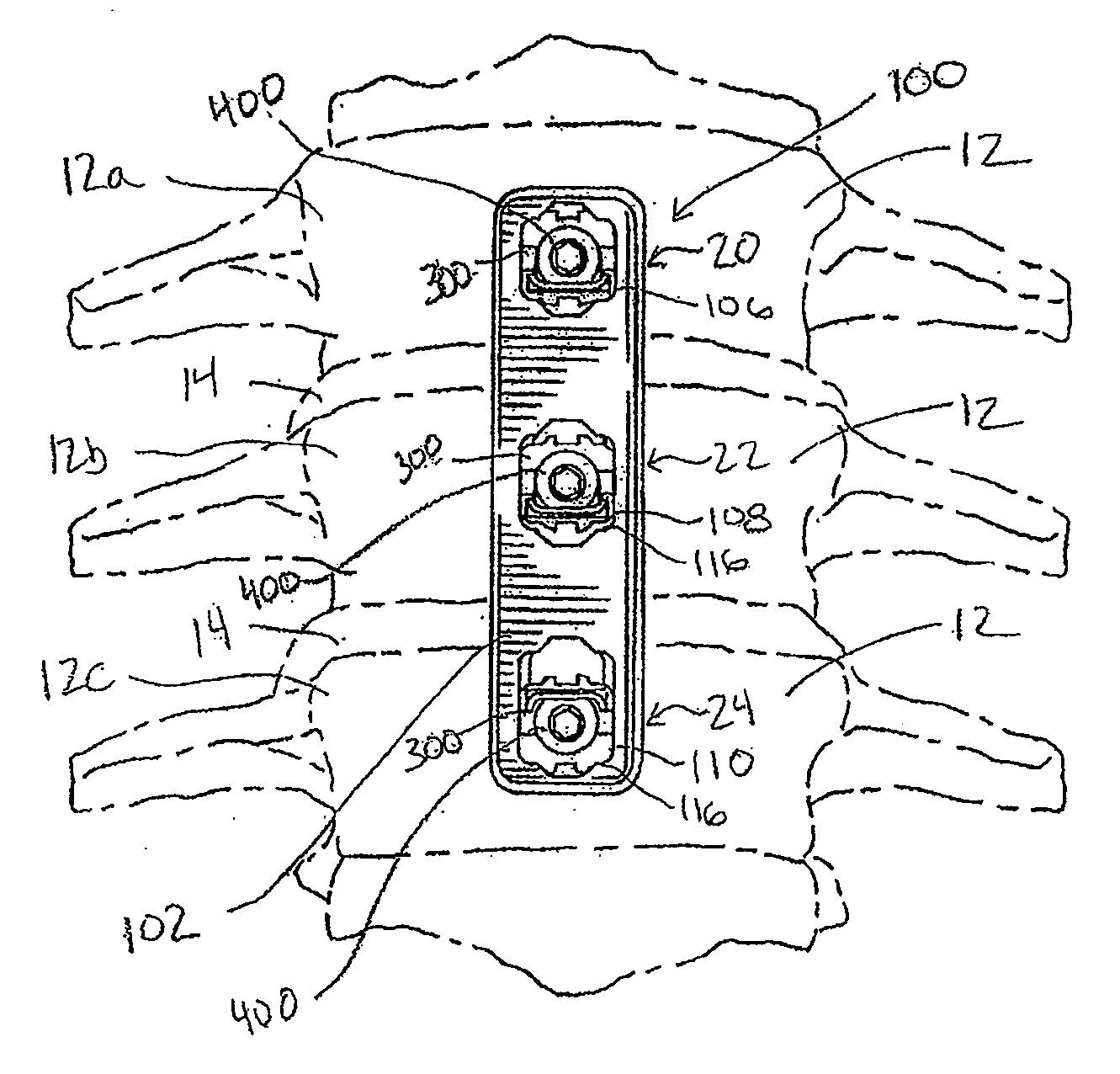
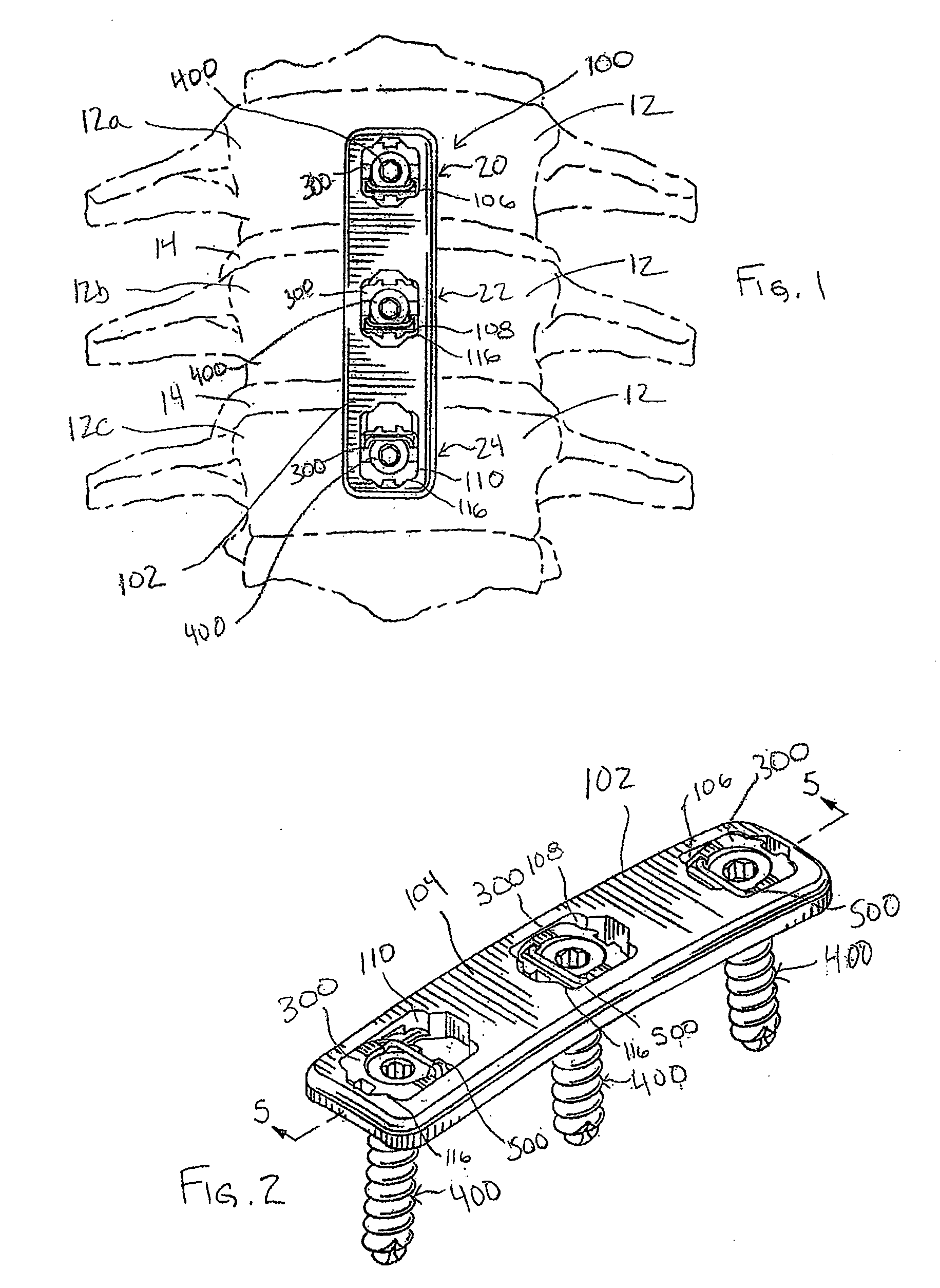
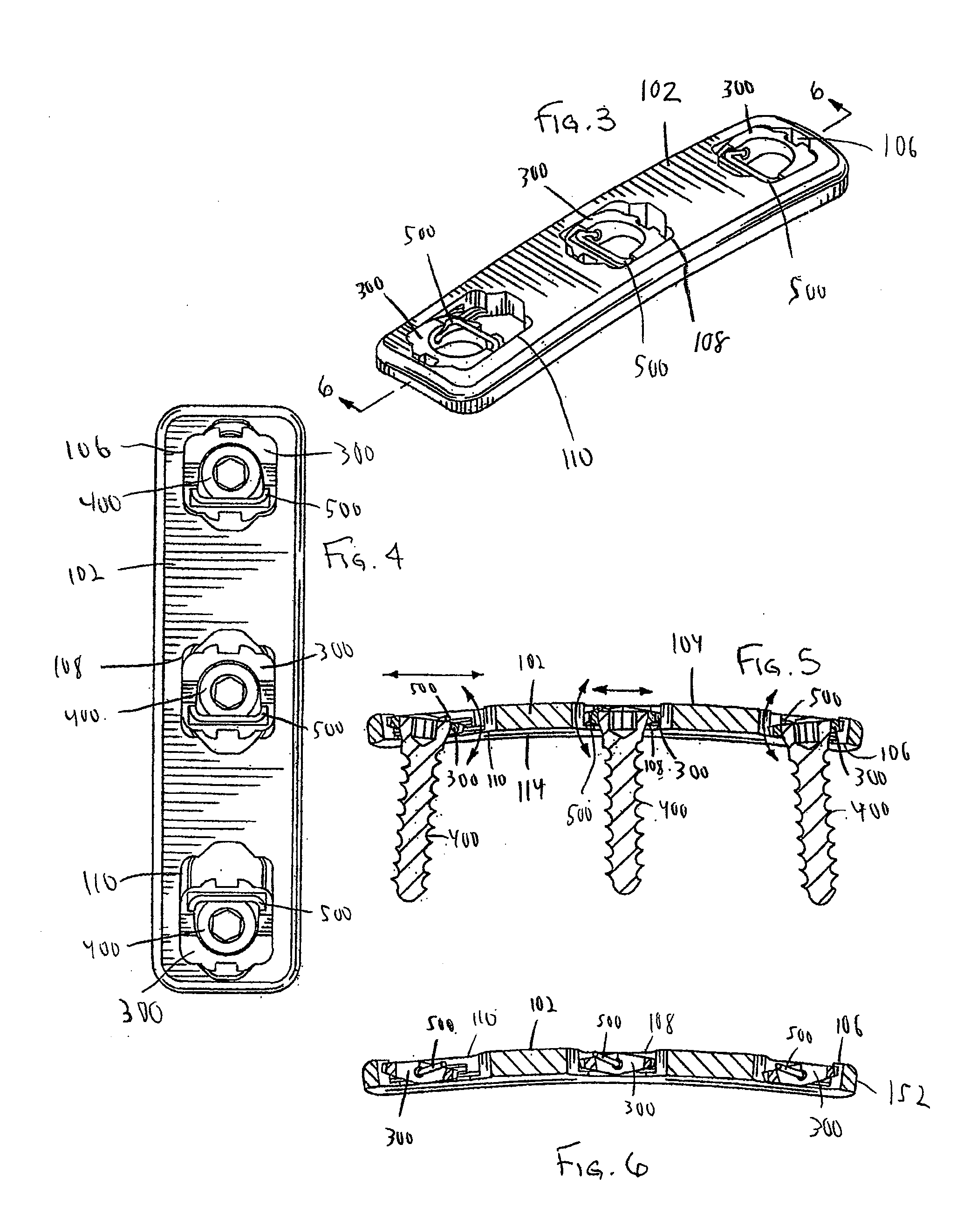
[0165]Generally speaking, pursuant to these various embodiments, bone plate systems are disclosed herein for securing a plurality of bones 12 in a desired orientation and arrangement. In some forms, the bone plate system utilizes a dynamized plate with dynamic bores so that bones may compress and shift toward each other, such as with dynamic or dynamized bone plate systems 100, 1100, 1700 shown in FIGS. 1, 36, and 45, respectively. In other forms, bone plate systems utilize standard plate members with throughbores of the same size, such as standard bone plate systems 200, 1200 shown in FIGS. 7, 43.

[0166]Referring now to the figures, and in particular to FIGS. 1-6, a dynamized bone plate system 100 is shown. Referring to FIG. 1, the dynamized bone plate system 100 assists in the healing and repair of damaged, fractured, or broken bones. In the exemplary illustration of FIG. 1, bones 12 are adjacently located vertebrae of a spine, each spaced by a spinal disc 14. The bone plate system...


PUM


Abstract

Bone plate systems are provided for surgical implants and bone repair. The bone plate is multi-tiered for receiving bone anchors screws for securing a plurality of bones or bone fragments in a desired relationship. The plate members include throughbores for receiving a pivot base therein, with head ends of the bone anchors being secured in the pivot bases. The throughbores may permit and define a translation path for the pivot base and the bone anchor secured therein relative to the plate. Pivot members extending between the pivot base and the plate member facilitate pivoting and optional translation of the pivot base relative to the plate. With the bone anchor seated within the pivot base, an apparatus for inhibiting screw back out is employed.

Description

CROSS-REFERENCE TO RELATED APPLICATIONS[0001]This application claims priority to U.S. Provisional Application Ser. No. 60 / 947,873, filed Jul. 3, 2007, and entitled “Bone Plate System”; and U.S. Provisional Application Ser. No. 61 / 024,287, filed Jan. 29, 2008, and entitled “Monoplate Bone Plate Guide,” which are both hereby fully incorporated by reference as if set forth herein.FIELD OF THE INVENTION[0002]The invention relates to bone plate systems and, more particularly, to a bone plate system that allows for motion of the bone anchors relative to the bone plate member.BACKGROUND OF THE INVENTION[0003]There are presently many different types of plate and fixture systems for securing two or more bones or bone fragments in relative position so that the bones may fuse or heal, or so that tissue adjacent the bones may heal without disruption from the movement of the secured bones. As used herein, the term bone may refer to a bone, or a bone fragment or portion, and the term may refer to...

Claims


Application Information

Patent Timeline
Patent Type & Authority Applications(United States)
IPC IPC(8): A61B17/70
CPCA61B17/1671A61B17/1728A61B17/1757A61B17/7059A61B17/8038A61B2019/461A61B17/8047A61B17/808A61B17/8888A61B17/8894A61B17/8042A61B2090/061
Inventor PERROW, SCOTT J.FREDIN, BRADFILIZETTI, CRAIG
Owner PIONEER SURGICAL TECH INC
Why Eureka
Try Eureka