Laundry treatment machine and door switch thereof

Inactive Publication Date: 2009-03-12
LG ELECTRONICS INC
View PDF15 Cites 2 Cited by
  • Summary
  • Abstract
  • Description
  • Claims
  • Application Information

AI Technical Summary

Benefits of technology

[0029]In short, the switch housing unit is a predetermined distance apart from the cabinet. Thus, water flown along the cabinet may be able to be discharged through the space between the cab

Problems solved by technology

Conventionally, water flown along the front panel is highly likely to infiltrate into the switch housing unit during a water leak test or during a typical washing operation.
If water infiltrates i

Method used


Image

  • Laundry treatment machine and door switch thereof
  • Laundry treatment machine and door switch thereof
  • Laundry treatment machine and door switch thereof

Examples


Embodiment Construction

[0034]The present invention will hereinafter be described in detail with reference to the accompanying drawings in which exemplary embodiments of the invention are shown, and taking a drum-type washing machine as an example of a laundry treatment machine.

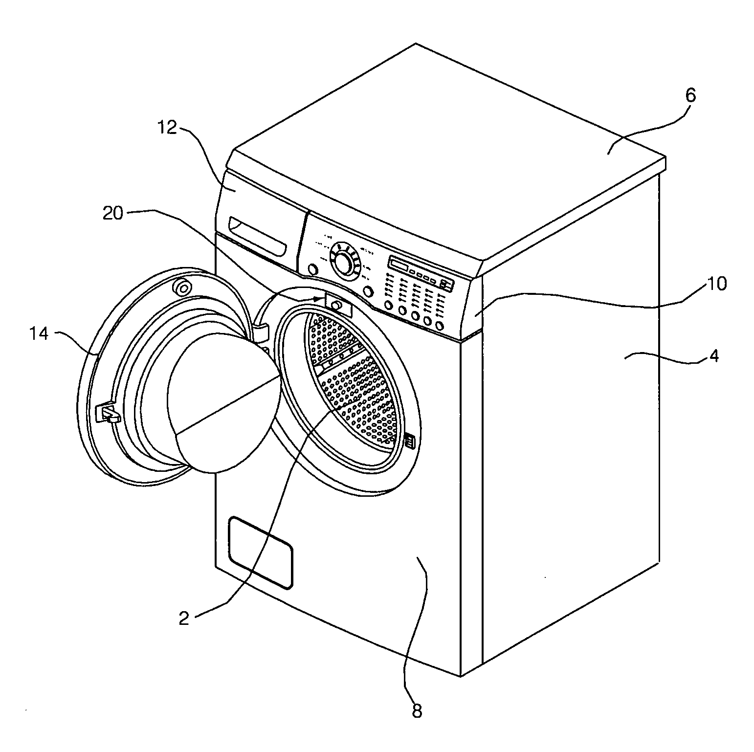
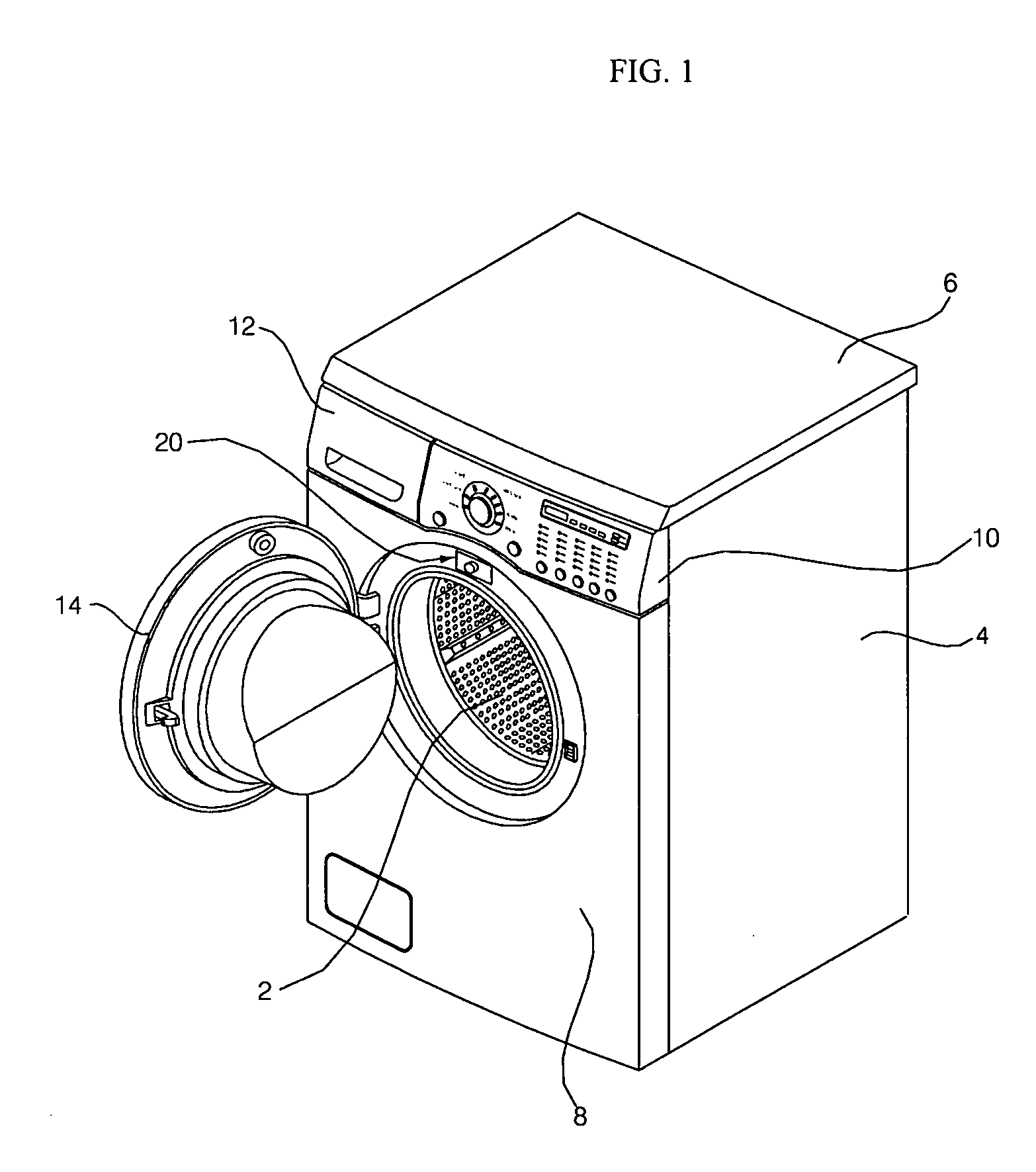
[0035]FIG. 1 illustrates a perspective view of a drum-type washing machine according to an exemplary embodiment of the present invention. Referring to FIG. 1, the drum-type washing machine includes a cabinet, which forms the exterior of the drum-type washing machine, a tub (not shown), which is installed in the cabinet and holds wash water, and a drum 2, which is installed in the tub and holds laundry.

[0036]The cabinet includes a cabinet main body 4, which is open at the top or the front of the cabinet main body 4, a top cover 6, which is installed so as to cover the top of the cabinet main body 4, and a front panel 8, which is installed so as to cover the front of the cabinet main body 4 and has a laundry inlet opening through whic...


PUM


Abstract

A laundry treatment machine and a door switch thereof are provided. The door switch includes a switch housing unit, which is a predetermined distance apart from a cabinet. Thus, water flown along the cabinet may be able to be discharged through the space between the cabinet and the switch housing unit. Therefore, it is possible to minimize the infiltration of water into the switch housing unit and to improve the durability and the safety of the door switch.

Description

[0001]This application claims priority from Korean Patent Application No. 10-2007-0089504 filed on Sep. 4, 2007 in the Korean Intellectual Property Office, the disclosure of which is incorporated herein by reference in its entirety.BACKGROUND OF THE INVENTION[0002]1. Field of the Invention[0003]The present invention relates to a laundry treatment machine and a door switch thereof, and more particularly, to a laundry treatment machine and a door switch thereof, which contributes to the improvement of the durability and the safety of a laundry treatment machine by preventing the infiltration of water into a switch housing unit.[0004]2. Description of the Related Art[0005]Laundry treatment machines are classified into washing machines removing dirt or dust from clothes or bedclothes by using water and detergent and using mechanical operations, dryers drying wet laundry by using a dry, hot wind generated by a heater and using mechanical operations, and combination washer dryers performi...

Claims


Application Information

Patent Timeline
IPC IPC(8): H01H35/00D06F39/14
CPCD06F39/14D06F37/28D06F37/42D06F37/10D06F2105/44
Inventor KIM, KYUNG TAE
Owner LG ELECTRONICS INC
Why Eureka
Try Eureka