Packaging process employing a closure orifice seal vent

a technology of venting and sealing vents, applied in the direction of packaging, packaged goods types, instruments, etc., can solve the problems of easy bucklers or collapses less desirable packaging 30/b>, and easy collapse of container walls during labeling processes or stacking processes. , to achieve the effect of significantly reducing minimizing, if not eliminating, the infiltration of cooling water

Active Publication Date: 2006-10-10
SEAQUIST CLOSURES FOREIGN
View PDF17 Cites 27 Cited by
  • Summary
  • Abstract
  • Description
  • Claims
  • Application Information

AI Technical Summary

Benefits of technology

[0027]Contrary to conventional wisdom regarding improved sealing techniques, the inventor of the present invention has discovered that cooling water infiltration can be significantly minimized, if not eliminated, by breaching a conventional lid / spout seal with a venting system incorporated to function in specific ways during the packaging process. Surprisingly, venting the closure system during the packaging process has been found, contrary to initial expectations, to greatly minimize, if not eliminate, cooling water infiltration.
[0030]The invention process can accommodate efficient, high-quality, high-speed, large volume manufacturing techniques with a reduced product reject rate.
[0031]The present invention provides a process for minimizing moisture accumulation in a product package. The process comprises the steps of:
[0042](F) permitting the external ambient atmosphere to enter the closed spout through the vent channel to the internal atmosphere within the closed spout as the package cools and the pressure of the internal atmosphere within the closed spout starts to decrease whereby the entering external ambient atmosphere minimizes the transient pressure differential between the internal atmosphere within the closed spout and the external ambient atmosphere so that the amount of water and / or water vapor entering past the closed lid and entering the closed spout past the first and second engaging surfaces and / or through the vent channel is minimized and whereby, after equalization between the pressure of the internal atmosphere and the pressure of the external ambient atmosphere, water vapor in the internal atmosphere within the closed spout can flow out of the closed spout through the vent channel in response to a water vapor gradient established when the external ambient atmosphere humidity is less than the internal atmosphere humidity.

Problems solved by technology

However, it has been found that such a package 30 may be less desirable with some types of products that undergo certain kinds of processing.
If the package container 32 is made of a thermoplastic material, the heated container material loses much of its strength when it is hot, and the container wall can easily buckle or collapse during labeling processes or stacking processes.
However, as the temperature of a package decreases, the internal atmosphere within the closed spout cools, and the internal pressure begins to decrease.
However, the presence of water or water vapor on the deck 50 under the lid 70 and also inwardly of the lid spout seal region is undesirable from the standpoint of consumer perception when the consumer later opens the package by lifting the lid 70.
Water under the closure lid in the dispensing orifice region may be regarded by the consumer as a problem with product quality or sanitary conditions.
If a product manufacture had not properly treated the cooling spray water to inhibit the growth of mold, bacteria, etc., then the presence of water within the internal portion of the closure could lead to growth of mold, bacteria, etc.
For a typical low-cost, disposable, dispensing closure molded from thermoplastic material, the inventors have been unable to design a readily manufactured closure that is easily openable by the consumer and that has an essentially 100% leak-tight seal to prevent cooling water ingress in response to a partial vacuum within the package during package cool-down.

Method used


Image

  • Packaging process employing a closure orifice seal vent
  • Packaging process employing a closure orifice seal vent
  • Packaging process employing a closure orifice seal vent

Examples


Embodiment Construction

[0056]This specification and the accompanying drawings disclose only one specific form of the process of the invention. The invention is not intended to be limited to the described embodiment, however. The scope of the invention is pointed out in the appended claims.

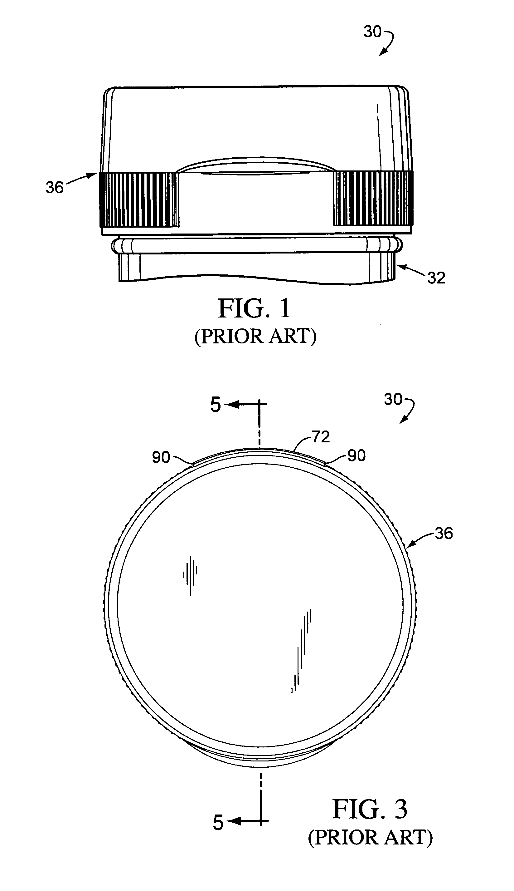
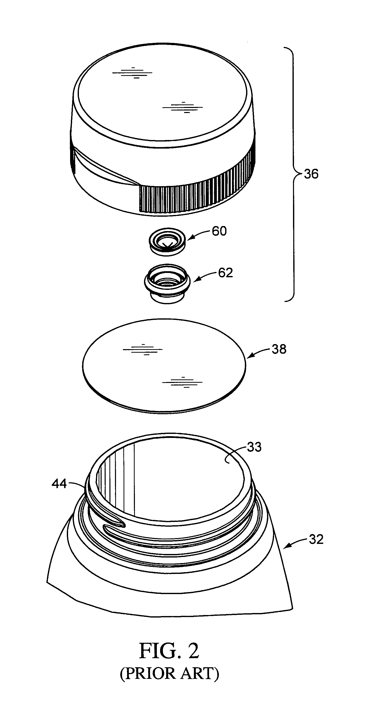
[0057]The process of this invention is suitable for use with a variety of conventional or special containers having various designs, the details of which, although not illustrated or described, would be apparent to those having skill in the art and an understanding of such containers. Therefore, the particular container illustrated and described herein is not intended to limit the broadest aspects of the present invention.

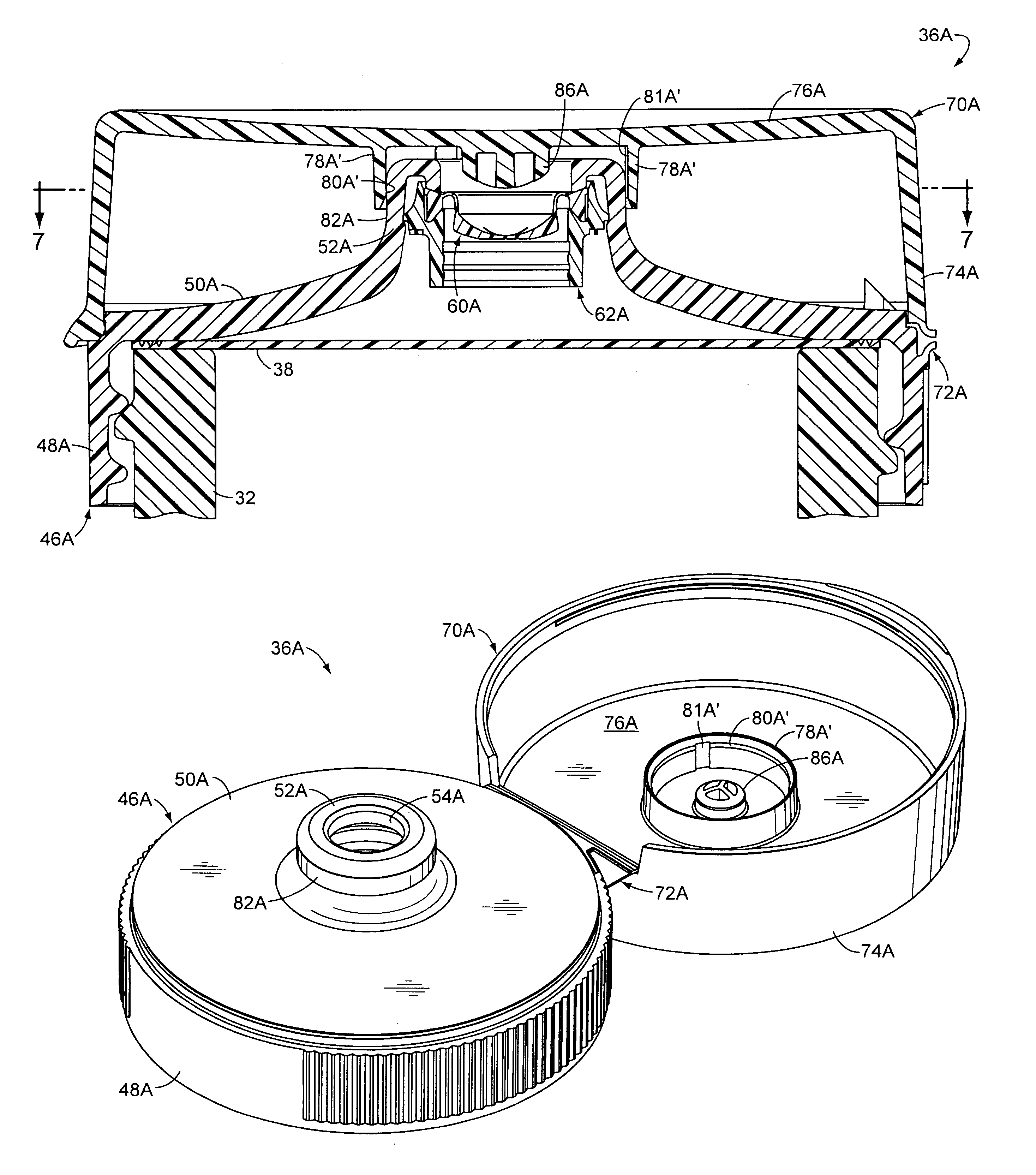
[0058]According to the process of the present invention, a product can be provided and processed in a package which can employ a closure with a vent system which will function surprisingly to minimize the accumulation of moisture inside the package when the package is processed through a cool water show...


PUM

PropertyMeasurementUnit
widthaaaaaaaaaa
radial thicknessaaaaaaaaaa
diameteraaaaaaaaaa

Abstract

A process is provided for minimizing moisture accumulation in a product package that is sprayed with a cool water shower. The product is placed in a container, and a closure is installed on a container. The product is heated before it is placed in the container or during its placement in the container, or after it is placed in the container, or while the closure is being installed on the container, or after the closure has been installed on the container. The internal atmosphere within the closed closure is allowed to expand from the heat and to vent through a vent channel. The package is cooled with a cooling water shower, and the vent channel minimizes the transient pressure differential so as to minimize the amount of water infiltration into the closure.

Description

CROSS-REFERENCE TO RELATED APPLICATION(S)[0001]Not applicable.STATEMENT REGARDING FEDERALLY SPONSORED RESEARCH OR DEVELOPMENT[0002]Not applicable.REFERENCE TO A MICROFICHE APPENDIX[0003]Not applicable.TECHNICAL FIELD[0004]This invention relates to a packaging process employing a vented closure system for a container.BACKGROUND OF THE INVENTION AND TECHNICAL PROBLEMS POSED BY THE PRIOR ART[0005]The upper portion of a conventional package 30 is shown in FIG. 1, and the package includes a container 32 which has been filled with a fluent product (not visible). The container 32 has an upper opening 33 (FIGS. 2 and 5), and the top of the container 32 is covered or closed with a closure system or closure 36 (FIG. 1) which is mounted to the top of the container 32.[0006]An optional “liner” seal member 38 (FIGS. 2 and 5) may be employed as part of the closure system. Typically, such an optional liner 38 is a membrane that includes at least one layer of thermoplastic material that can be heat...

Claims


Application Information

Patent Timeline
Patent Type & Authority Patents(United States)
IPC IPC(8): B65B7/28B65B63/08B65D51/16
CPCB65D47/2031B65D51/1611
Inventor DANKS, CHRISTOPHER A.
Owner SEAQUIST CLOSURES FOREIGN
Why Eureka
Try Eureka