
Thermal recording apparatus, image forming method, and printed object

a recording apparatus and image technology, applied in the field of thermal recording apparatus, can solve the problems of difficult control of gradation on the pixel, density of dots, etc., and achieve the effect of reducing the printing miss of the white backing and adhesion failur

Inactive Publication Date: 2009-03-12
DAI NIPPON PRINTING CO LTD
View PDF15 Cites 3 Cited by
  • Summary
  • Abstract
  • Description
  • Claims
  • Application Information

AI Technical Summary

Benefits of technology

[0028]According to the present invention, it is possible to provide a thermal recording apparatus, etc., which provide smooth halftone images without being influenced by heat accumulated in a thermal head, which mitigate printing miss of a white backing and adhesion failure, which would occur when a white backing is applied or transfer to a polycarbonate sheet or the like is performed, and which allow obtainment of halftone images which do not have nonuniformity associated with overprinting at highlight portions.

Problems solved by technology

However, when it melts and transfers a color material, it is susceptible to the density of dots as well as to adjacent dots, and encounters difficulty in controlling gradation on a pixel-by-pixel basis.

Method used


Image

  • Thermal recording apparatus, image forming method, and printed object
  • Thermal recording apparatus, image forming method, and printed object
  • Thermal recording apparatus, image forming method, and printed object

Examples


second embodiment

[0109]Next, the thermal recording apparatus of the present invention will be described.

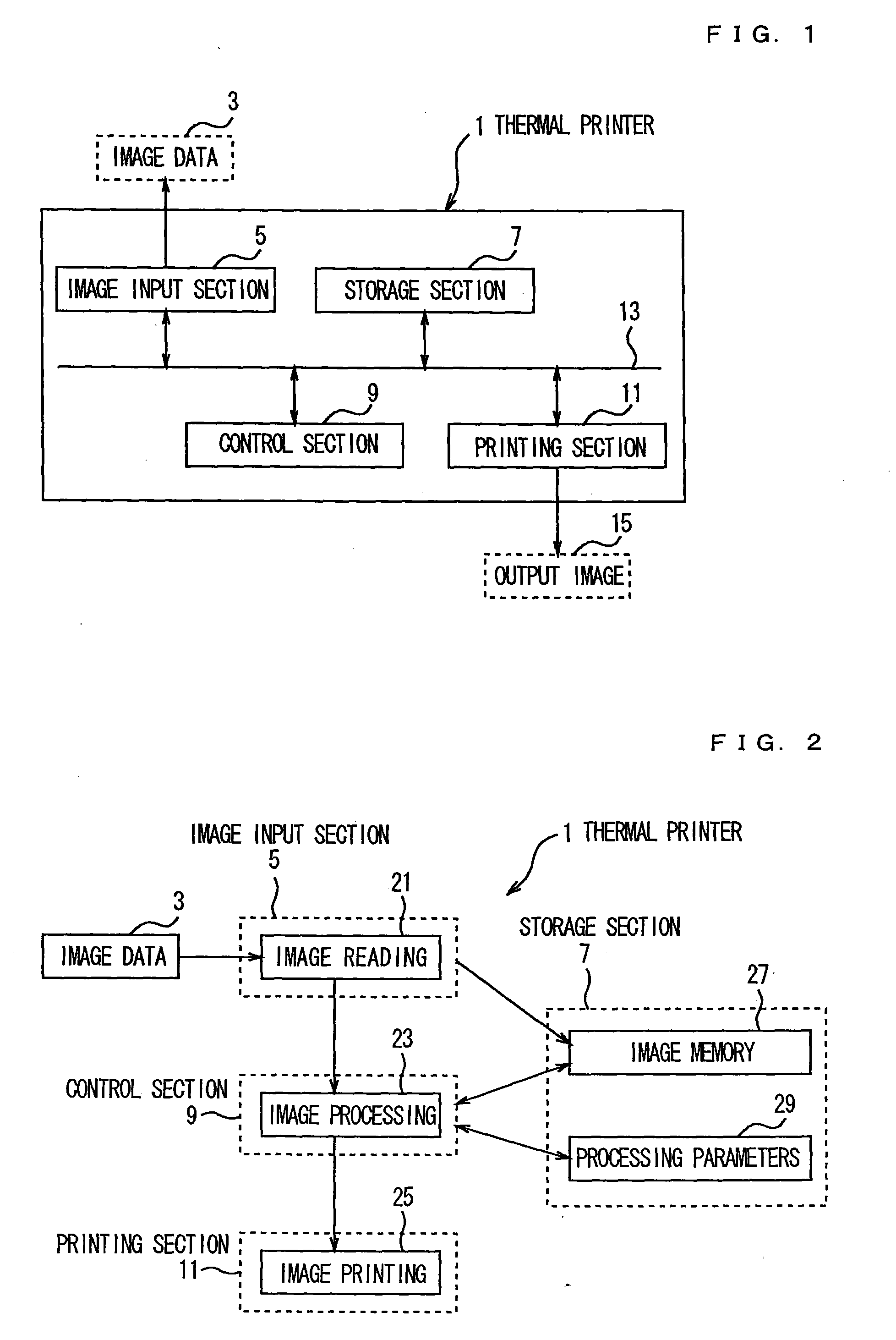
[0110]In the second embodiment, the structure and the processing details of the thermal printer 1 are generally the same as those in the first embodiment shown in FIGS. 1 and 2.

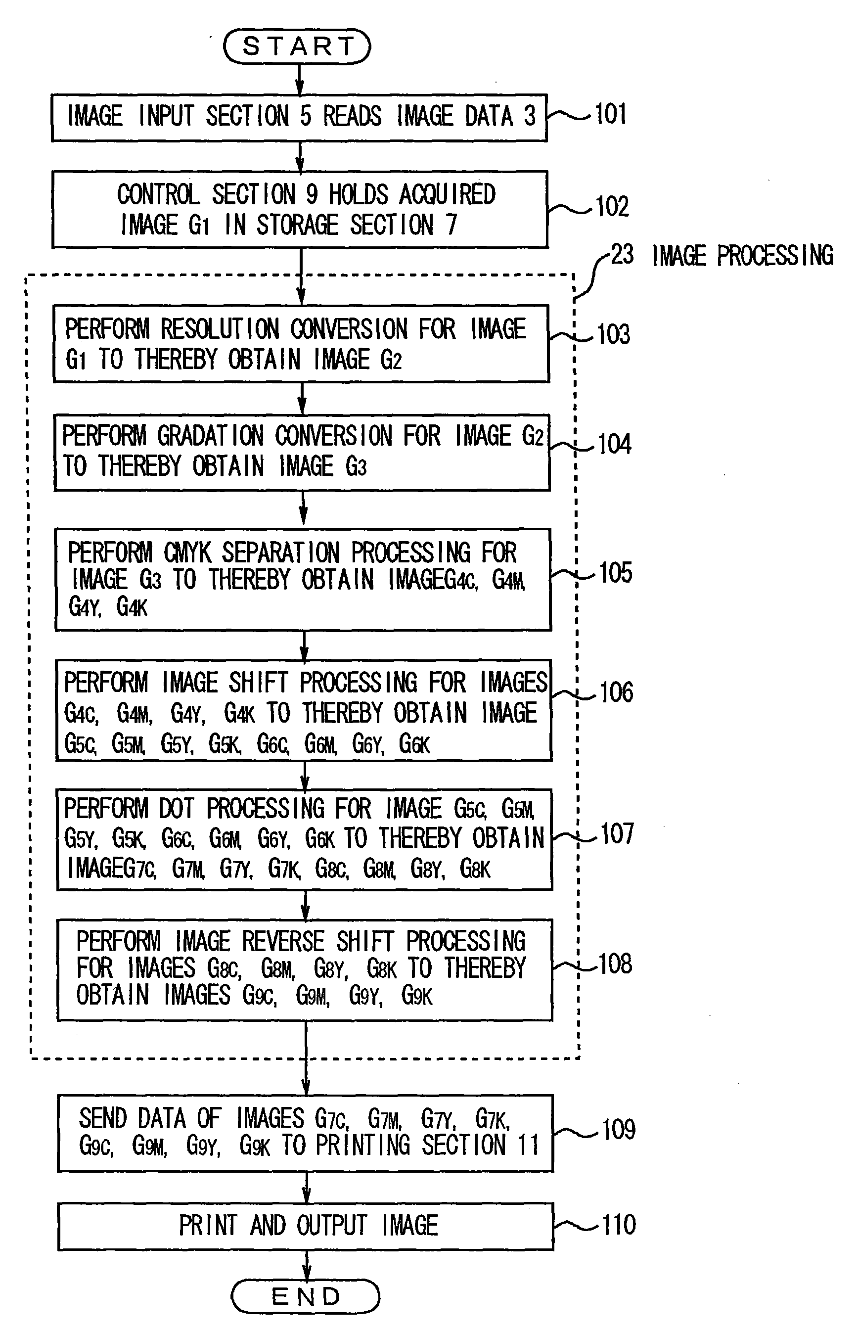
[0111]The second embodiment differs from the first embodiment in the image shift processing (step 106 of FIG. 4) of the image processing 23. That is, in the second embodiment, the number of pixels by which image data are shifted is changed on a color-by-color basis among cyan (C), magenta (M), yellow (Y), and black (K). Thus, steps formed when images of the respective colors are overprinted in a dot-on-dot fashion are decreased, and printing miss and adhesion failure can be eliminated.

first embodiment

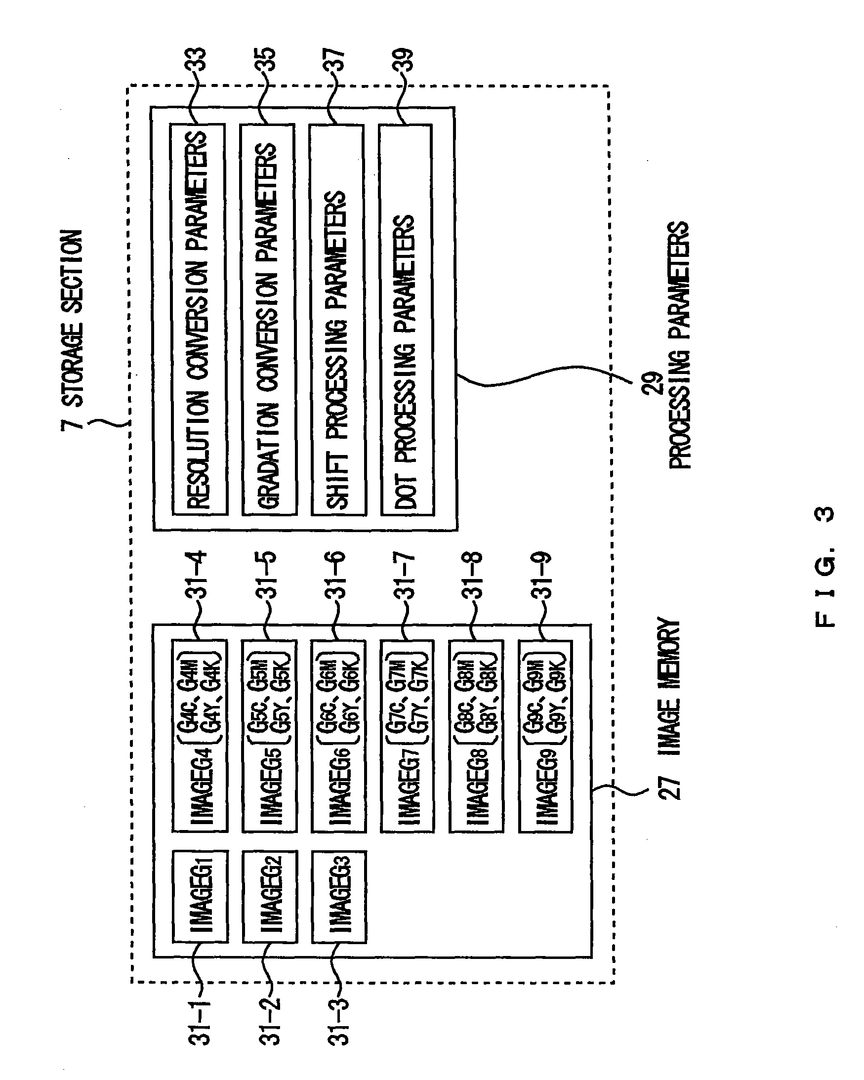
[0112]The flow of the processing is identical with that of the first embodiment from step 101 to step 105 of FIG. 4. That is, after having read the image data 3 through the image input section 5 (step 101), the control section 9 holds the acquired image G1 31-1 in the image memory 27 of the storage section 7 (step 102). Subsequently, the control section 9 performs the resolution conversion processing; i.e., converts the resolution of the image G1 31-1 in accordance with the resolution of the thermal printer 1 to thereby produce the image G2 31-2 (step 103). The control section 9 then performs the gradation conversion; i.e., converts the gradation of the image G2 31-2 to thereby produce the image G3 31-3 (step 104), and converts the image G3 31-3 to CMYK data (CMYK separation processing) to thereby produce the image G4 31-4 (step 105), and stores it in the image memory 27 of the storage section 7.

[0113]The image G4 31-4 obtained through the gradation conversion is composed of four im...

third embodiment

[0139]Next, the thermal recording apparatus of the present invention will be described.

[0140]In the third embodiment, the structure and the processing details of the thermal printer 1 are generally the same as those in the first embodiment shown in FIGS. 1 and 2.

[0141]In the third embodiment, through partial modification of the flow of the image processing 23, the black (K) image or / and the yellow (Y) image are printed in single tone, to thereby increase the speed of the image printing 25 at the printing section 11, and reduce the amount of a material, such as ink, used for the printing.

[0142]The reason why the black (K) image, for example, may be printed in single tone is that in many cases black (K) is used at edge portions of an image, and it is unnecessary to obtain a smooth halftone image through double-tone printing. Further, since yellow (Y) is not noticeable in the printed image, in many cases, no problem arises even when the yellow (Y) image is printed in single tone.

[0143]...


PUM


Abstract

A control section 9 of a thermal printer 1 performs resolution conversion, gradation conversion, and CMYK color separation for input image data 3. After that, for image data of each color, the control section 9 performs shift processing for double-tone printing, to thereby obtain two types of image data. The control section 9 performs dot conversion and reverse shift processing for these image data, and prints the two types of image data in a superposed state. In the shift processing, the control section 9 shifts the image data of each color by the number of pixels corresponding to the resolution of the thermal printer 1 and the number of lines per inch. At that time, the image data of each color may be shifted by the corresponding number of pixels which differs among the colors. Further, for some colors, single-tone printing is performed, rather than double-tone printing, to thereby reduce the number of times of overprinting. Further, dot-on-dot processing, which is special shift processing, is performed for image data of a color to be printed second or later. Image data combining is performed such that the image data having undergone the dot-on-dot processing is used in a highlight region, and the image data having undergone the ordinary shift processing is used in the remaining region.

Description

TECHNICAL FIELD[0001]The present invention relates to a thermal recording apparatus, etc., which provide smooth halftone images without being influenced by heat accumulated in a thermal head.BACKGROUND ART[0002]A thermal printer is an apparatus which heats the back of an ink ribbon superposed on a recording paper by means of a thermal head in order to thermally transfer the ink of the ink ribbon onto the recording paper, to thereby print an image on the paper. The ink ribbon is a thermal transfer sheet including a layer of thermally meltable color ink, and the recording paper is an image-receiving sheet such as a sheet of paper or a plastic sheet.[0003]The thermal head is a composed of a plurality of heat-generating resistors formed on a substrate in a row. The thermal printer includes a plurality of ink ribbons corresponding to a plurality of colors. The inks of the ink ribbons of the plurality of colors are transferred in a superposed state onto the recording paper at the same pos...

Claims


Application Information

Patent Timeline
Patent Type & Authority Applications(United States)
IPC IPC(8): B41J35/16
CPCB41J2/36H04N1/6027H04N1/506B41J2/52B41J2/315B41J2/32
Inventor TAKITA, HIROAKITAMURA, YOSHIHIKOOHKUBO, TAKAYUKI
Owner DAI NIPPON PRINTING CO LTD
Learn More