ATM communications system and method

a communication system and atm technology, applied in the field of telecommunications technology, can solve the problems of no intrinsic mechanism to mitigate the effect, no effective adaptation of the different requirements of the system user, error, etc., and achieve the effect of reducing the amount of control or overhead information and freeing the bandwidth

Inactive Publication Date: 2009-03-12
TELEFON AB LM ERICSSON (PUBL)
View PDF5 Cites 2 Cited by
  • Summary
  • Abstract
  • Description
  • Claims
  • Application Information

AI Technical Summary

Benefits of technology

[0013]An object of the invention is to minimise or to overcome this disadvantage.
[0014]A further object of the invention is the provision of an ATM adaptation layer to provide system flexibility to support a variety of system users.
[0016]The technique allows a reduction in the amount of control or overhead information that must be transmitted thus freeing bandwidth e.g. to provide additional payload capacity. The minicell length is determined implicitly or explicitly from a service type code that is provided in the cell header.

Problems solved by technology

A number of recommendations have been made for an adaptation layer to provide support of these services, but none of these has effectively accommodated the different requirements of the system users.
The loss or corruption of a sample can lead to an error occurring over an extended time period due to the memory and adaptation time constants contained within the coding process.
Backward adaptation coders tolerate isolated bit or sample errors—for example in ADPCM a click and noise distortion may be audible—but they have no intrinsic mechanism to mitigate the effects of long bursts of consecutive sample errors caused by loss or corruption of a AAL-CU mini-cell.
However, the complexity and increase in end-to-end delay that would result makes it unsuitable for the new AAL.
As a consequence, the loss or corruption of a mini-cell would cause the discard of the entire data packet generally.
In protocols based on retransmission, a noisy transmission environment could become swamped.
The specific requirements of these different types of system user cannot all be met by current ATM transmission protocols.
A particular problem with accommodation of these various users is that of determining the length of each minicell so the cells can be correctly delineated in the de-multiplexing process.
Further, some users may require variable length minicells.

Method used


Image

  • ATM communications system and method
  • ATM communications system and method
  • ATM communications system and method

Examples


Embodiment Construction

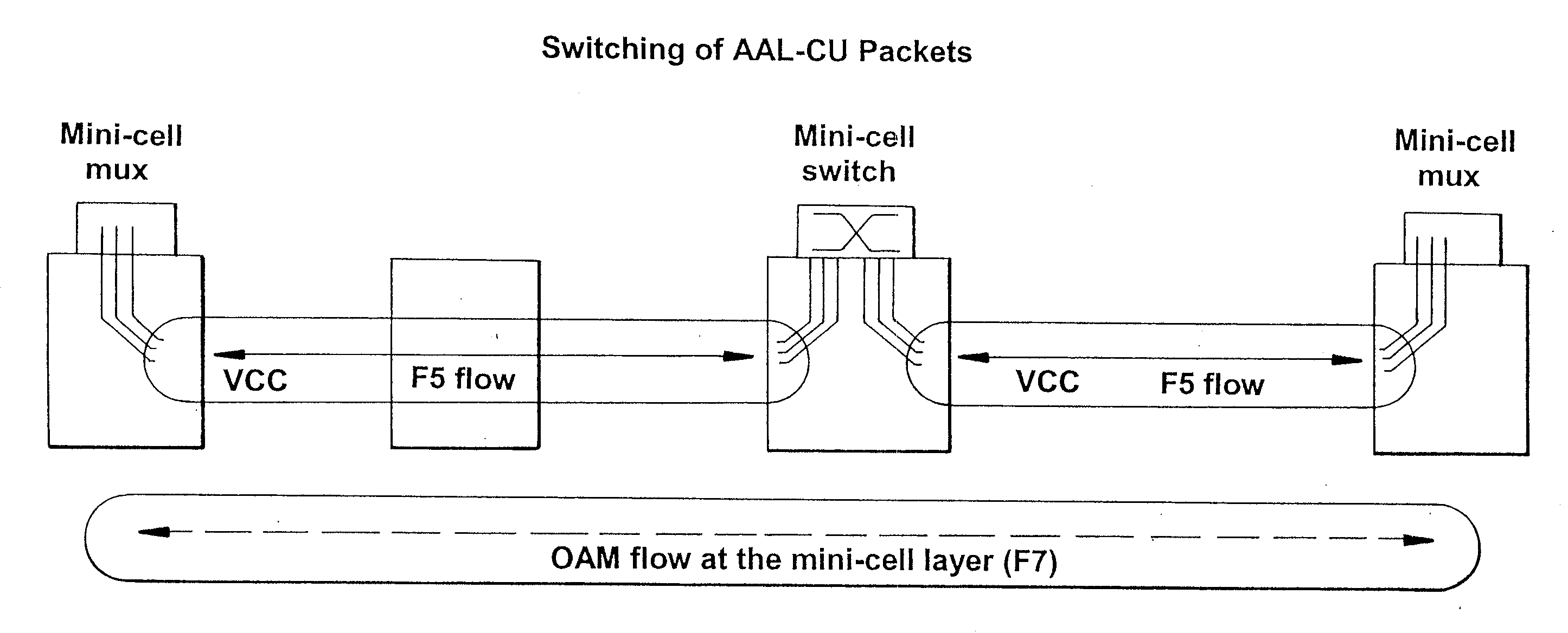
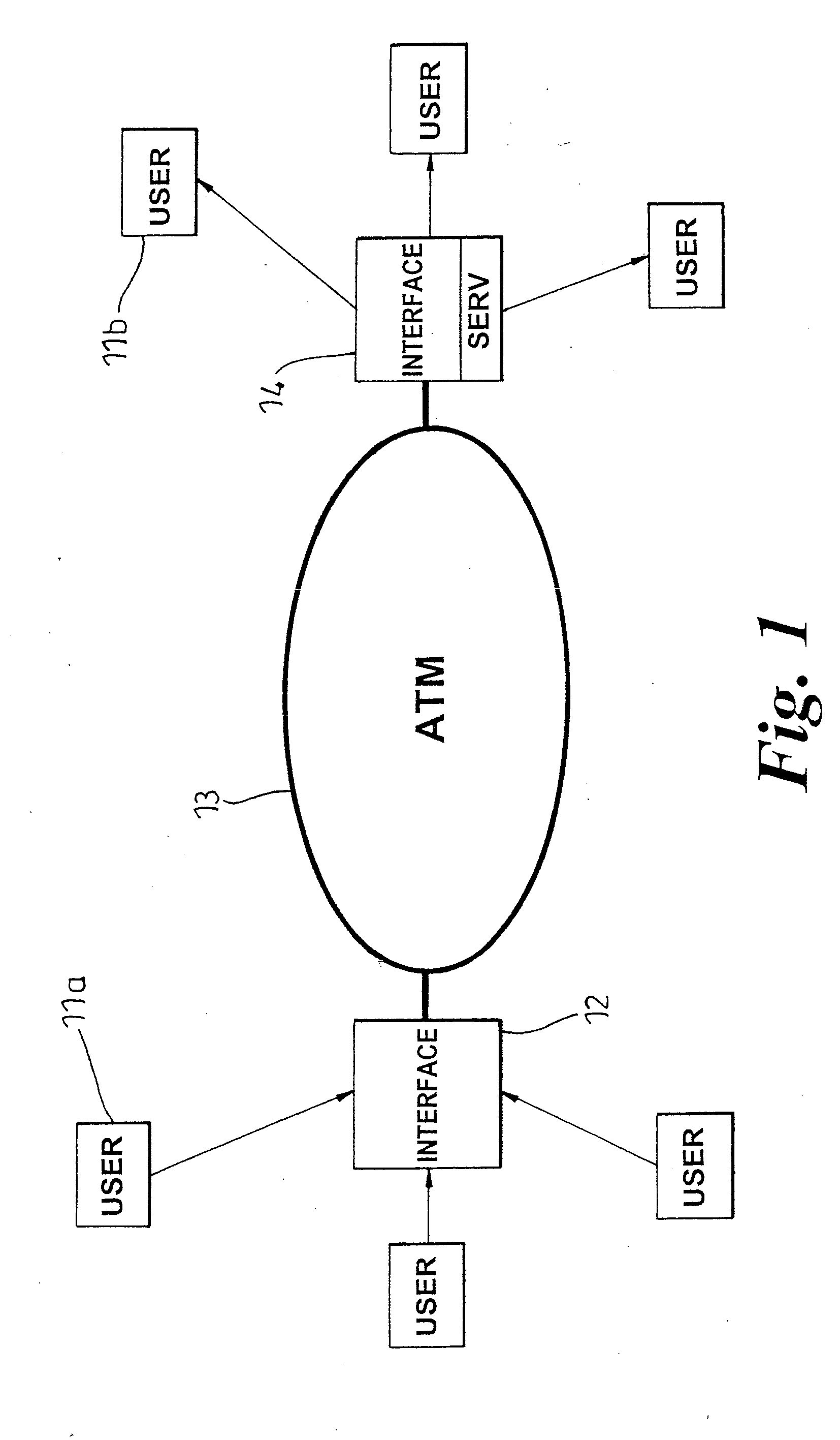
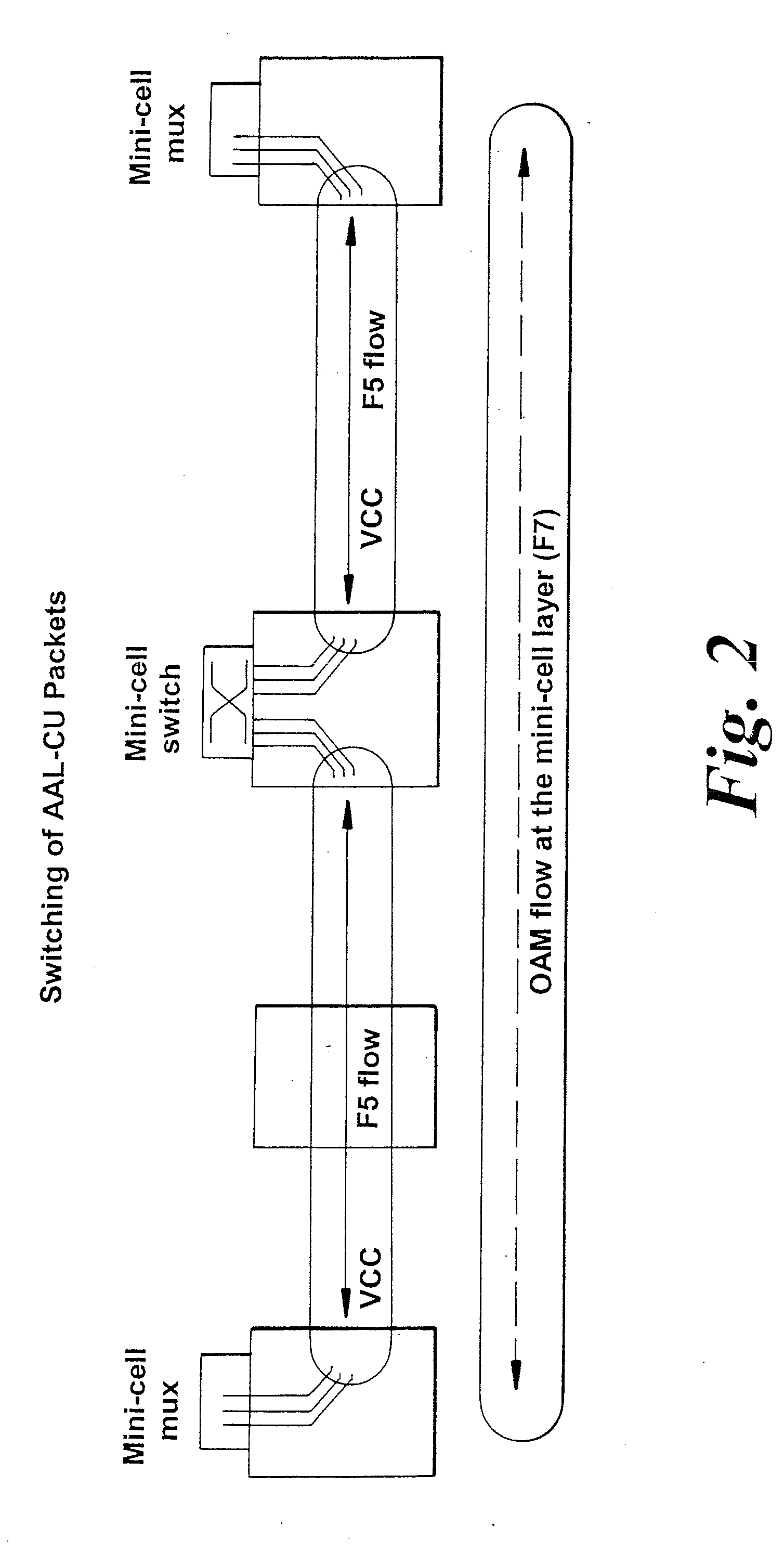
[0023]Referring first to FIG. 1, traffic from a number of users 11 is routed to an interface 12 where assembly of user minicells and multiplexing of those minicells into ATM cells is performed. The assembled ATM cells are provided with appropriate header information and are transmitted across the ATM network 13 to an egress interface 14 where cell disassembly and de-multiplexing is performed to recover the user traffic. An AAL-CU adaptation layer employed in the network of figure is separated into two parts, a Common Part Sub-layer (CPS) and a Service Specific Convergence Sub-layer (SSCS).

[0024]The list of identified requirements for the Common Part Sub-layer includes:[0025]support multiplexing of multiple users into a single connection;[0026]ability to delineate mini-cell boundaries within the ATM payload;[0027]error detection across AAL-CU common part information;[0028]protection against mis-concatenation due to ATM cell loss or mini-cell common part information corruption—to enab...


PUM


Abstract

Traffic from a number of different service type users is multiplexed into minicells for transmission over an ATM link. Service type information is transmitted in a service specific field and is stored. This stored information is used to derive length information to delineate the different length user minicells. The technique occupies less bandwidth than the conventional methods for transmitting cell length information.

Description

[0001]This invention relates to digital telecommunications systems and in particular to an arrangement and method for transmitting asynchronous transfer mode (ATM) traffic.BACKGROUND OF THE INVENTION[0002]A recent development in telecommunications technology has been the introduction of the asynchronous transfer mode (ATM) transmission technique. The asynchronous transfer mode (ATM) technology is a flexible form of transmission which allows various types of service traffic, e.g. voice, video or data, to be multiplexed together on to a common means of transmission, the traffic being carried in cells each having a header indicating its destination. The service traffic is adapted typically into 53 byte cells comprising 0.5 byte headers and 48 byte payloads such that the original traffic can be reconstituted at the far end of the ATM network. This form of adaptation is performed in the ATM adaptation layer (AAL). The technique allows large volumes of traffic to be handled reliably and e...

Claims


Application Information

Patent Timeline
Patent Type & Authority Applications(United States)
IPC IPC(8): H04L12/28H04L12/70H04Q11/04
CPCH04L2012/5652H04Q11/0478H04L2012/5672
Inventor BRUECKHEIMER, SIMON DANIELMAUGER, ROY HAROLD
Owner TELEFON AB LM ERICSSON (PUBL)
Why Eureka
Try Eureka