Steam turbine

Active Publication Date: 2009-03-12
KK TOSHIBA
View PDF10 Cites 6 Cited by
  • Summary
  • Abstract
  • Description
  • Claims
  • Application Information

AI Technical Summary

Benefits of technology

[0021]An object of the present invention is to provide a s

Problems solved by technology

These would result in hi

Method used


Image

  • Steam turbine
  • Steam turbine
  • Steam turbine

Examples


Example

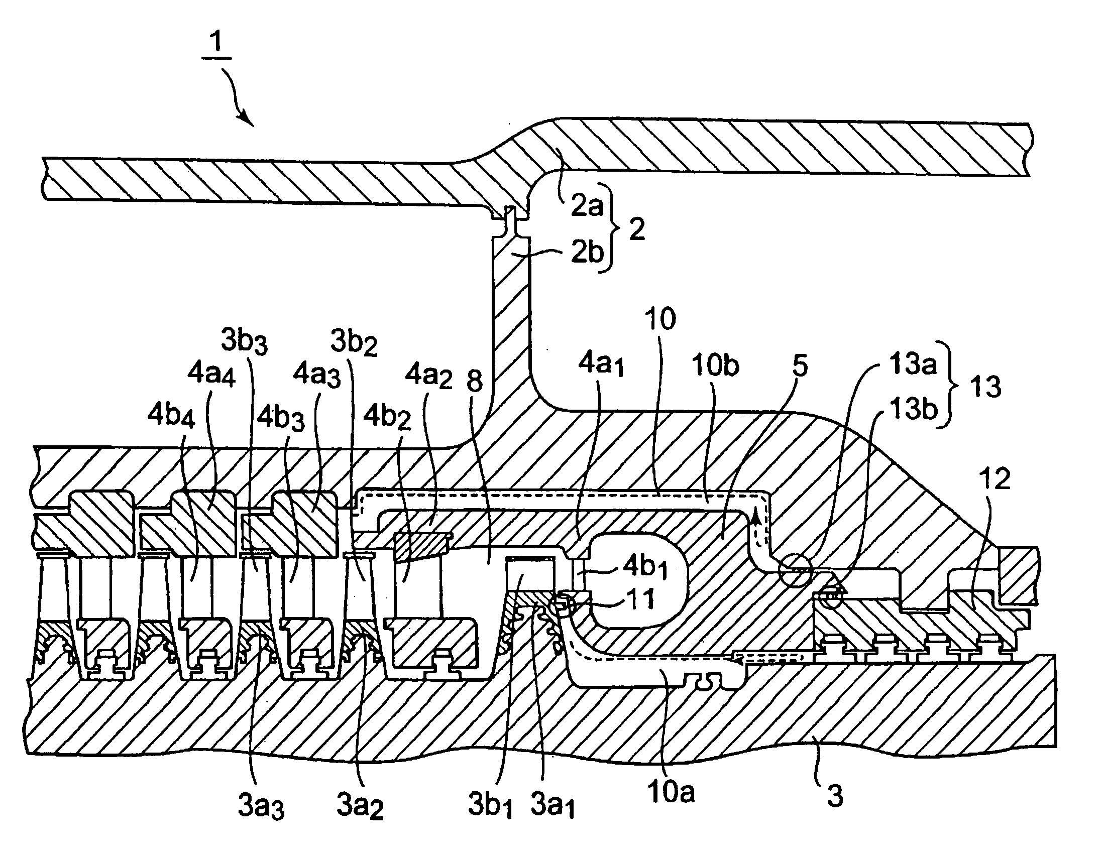
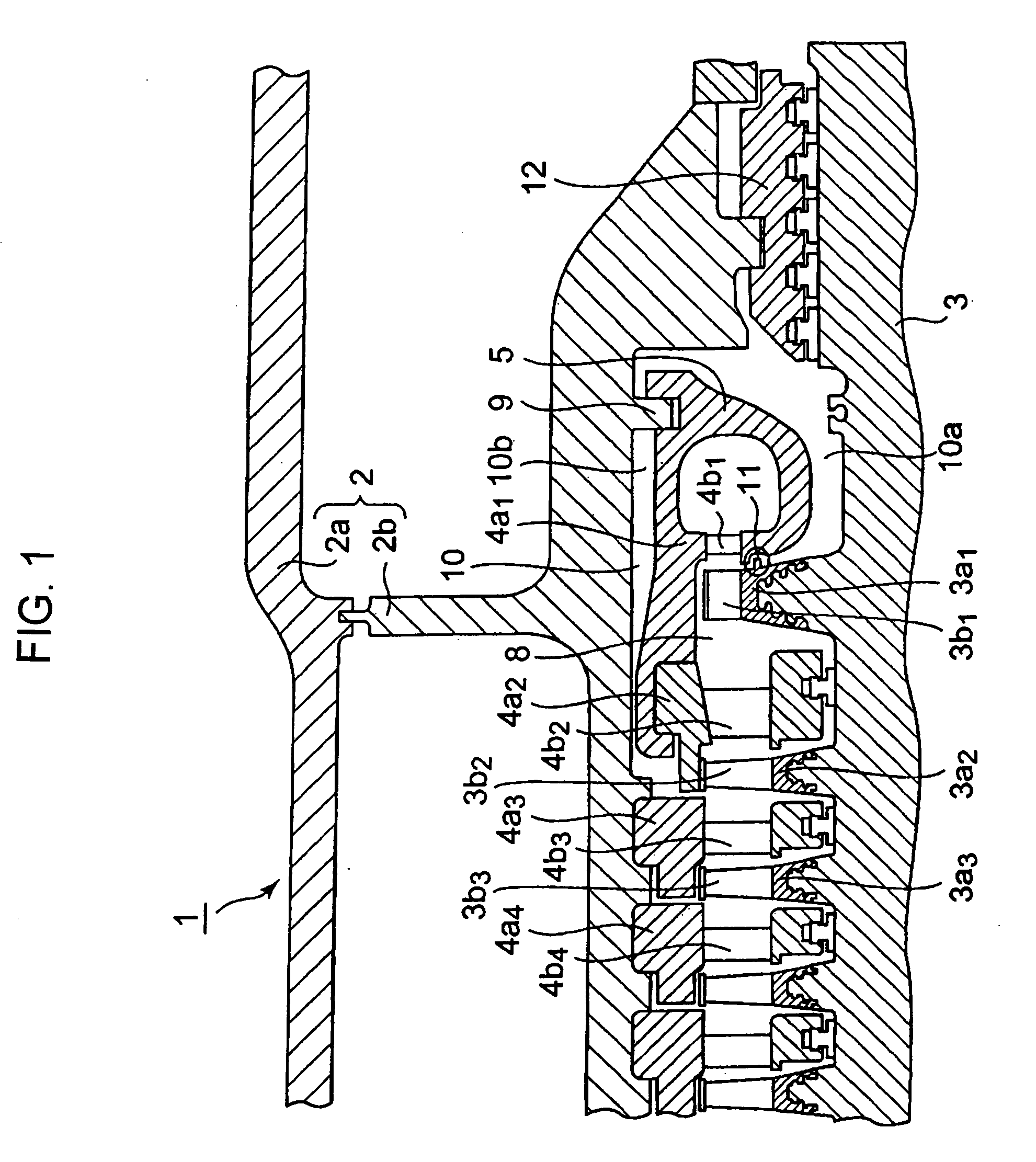
[0031]FIG. 1 is a schematic axial cross-sectional view of the first embodiment of steam turbine according to the present invention taken along a plane inclined by 45° from the vertical direction. In FIG. 1, the components same as those of the known steam turbine shown in FIGS. 5 and 6 are denoted respectively by the same reference symbols and will not be described any further unless necessary.

[0032]The steam turbine 1 of this embodiment has a casing 2, a turbine rotor 3 rotatably arranged in the casing 2 and nozzle diaphragms 4a1, 4a2, 4a3, . . . rigidly secured to the casing 2. The casing 2 includes an outer casing 2a and an inner casing 2b.

[0033]A plurality of moving blade stages 3a1, 3a2, 3a3, . . . are arranged on the turbine rotor 3, which is a rotating section of the steam turbine 1, in the axial direction from the upstream side to the downstream side. Each of the moving blade stages 3a1, 3a2, 3a3 has a plurality of moving blades, the plurality of moving blades of the moving ...


PUM


Abstract

A steam turbine has a stationary section, a turbine rotor, nozzle diaphragms, and a nozzle box. The stationary section includes a casing. The turbine rotor includes moving blade stages arranged in an axial direction. Each of the moving blade stages is provided with moving blades arranged in a circumferential direction, and rotatably provided in the casing. Each of the nozzle diaphragms has turbine nozzles arranged in the circumferential direction provided substantially coaxially with the turbine rotor by being secured to the stationary section. The nozzle box is supported on the stationary section and arranged at an upstream part of the moving blade stages substantially coaxially with the turbine rotor so as to lead steam flowing toward the turbine moving blades. The nozzle box holds at least two stages of the nozzle diaphragms.

Description

CROSS REFERENCES TO RELATED APPLICATIONS[0001]This application is based upon and claims the benefit of priority from the prior Japanese Patent Application No. 2007-215769, filed in the Japanese Patent Office on Aug. 22, 2007, the entire content of which is incorporated herein by reference.BACKGROUND OF THE INVENTION[0002]The present invention relates to a steam turbine and, more particularly, it relates to steam turbine designed to achieve a high efficiency by improving the nozzle box arrangement in the steam inlet section.[0003]Generally, a steam turbine comprises a rotatable turbine rotor, moving blade stages, a casing and nozzle diaphragms. The casing and the nozzle diaphragms constitute as a stationary section. The rotor is rotatably provided in the casing. The nozzle diaphragms are arranged substantially coaxially with the turbine rotor, supported on the casing. The moving blade stages are provided on the turbine rotor so as to rotate together with the turbine rotor. Each of th...

Claims


Application Information

Patent Timeline
IPC IPC(8): F01D1/02
CPCF01D9/047F05D2240/55F01D25/26
Inventor KAWAKAMI, HIROSHI
Owner KK TOSHIBA
Why Eureka
Try Eureka