Compression molding machine

Inactive Publication Date: 2006-12-21
BERRY PLASTICS CORP
View PDF21 Cites 7 Cited by
  • Summary
  • Abstract
  • Description
  • Claims
  • Application Information

AI Technical Summary

Benefits of technology

[0003] Although vertical axis carousel-type machines of the noted type have enjoyed substantial commercial acceptance and success, innovation remains desirable. In particular, in vertical axis carousel-type machines, the mold forces and the weight of the rotating equipment are parallel to the vertical axis of rotation, creating a bending moment with respect to the axis of rotation and the bearings and shaft that support the carousel. Carousel-type machines also require a substantial amount of valua

Problems solved by technology

Carousel-type machines also require a substantial amou

Method used


Image

  • Compression molding machine
  • Compression molding machine
  • Compression molding machine

Examples


Embodiment Construction

[0020] The disclosure of U.S. application Ser. No. 11 / 109,374 filed Apr. 19, 2005 is incorporated herein by reference.

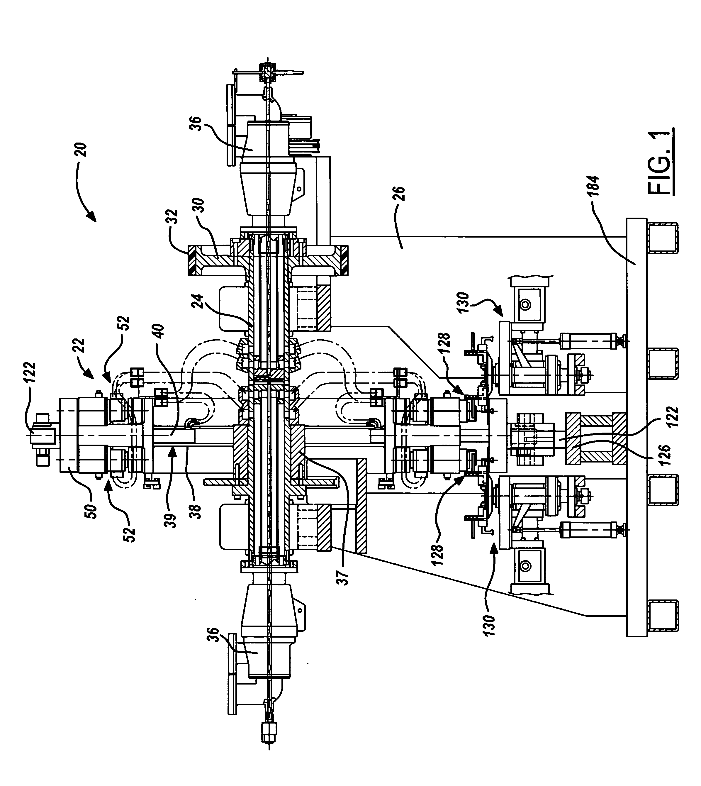
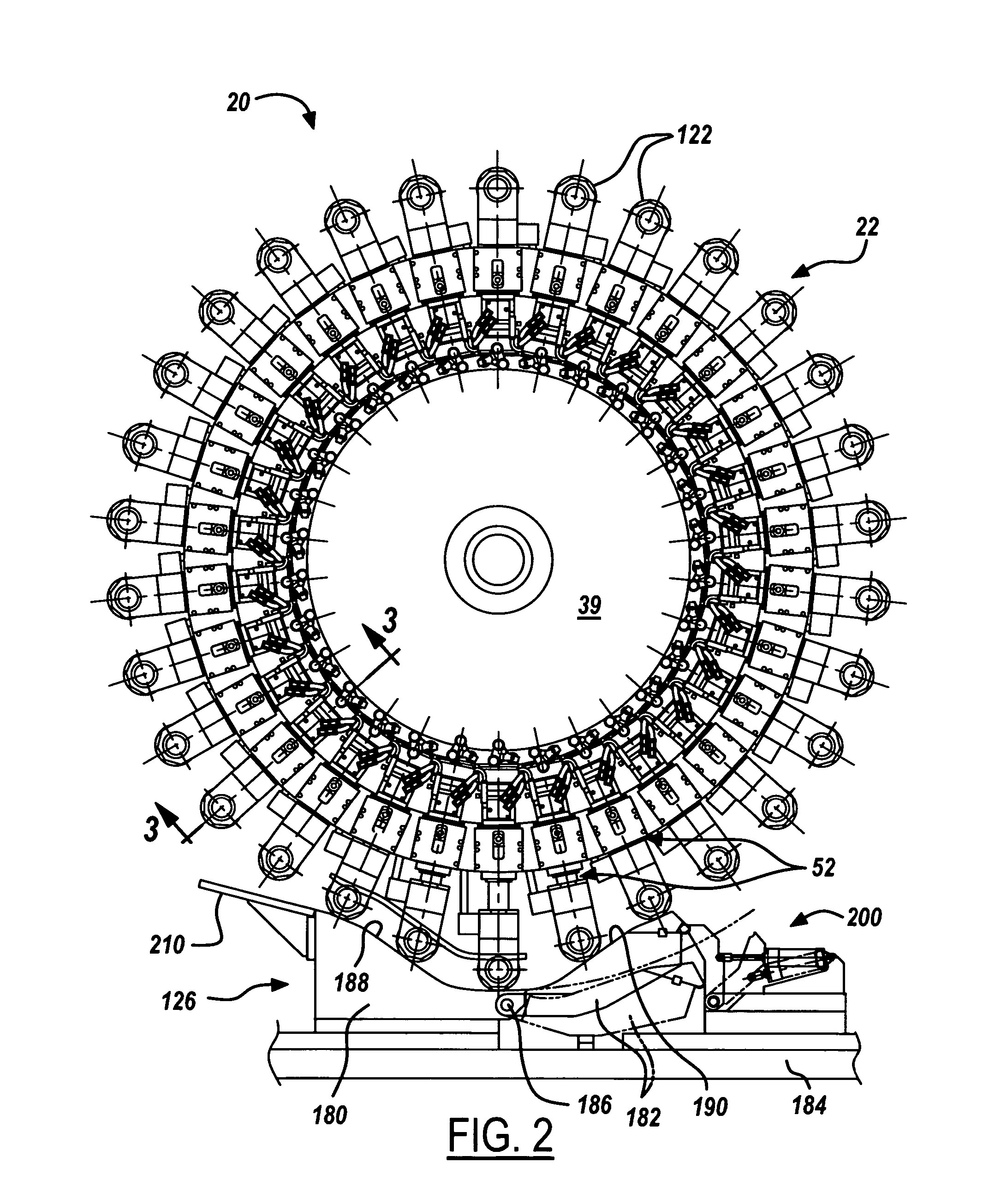
[0021]FIGS. 1-2 illustrate a machine 20 for compression molding plastic closure shells. Machine 20 includes a wheel 22 mounted on a shaft 24 between spaced supports 26. Shaft 24 is coupled by a pulley 30 and a belt 32 to a motor for rotating shaft 24 and wheel 22 around a horizontal axis. Wheel 22 includes a hub 37 (which may be part of shaft 24) and a support 39 extending radially from hub 37. Support 39 may comprise a disk or the like, or may be in the form of a plurality of angularly spaced radially extending support spokes 38. Each support spoke 38 is hollow at its outer end. A rod 40 is slidably supported by sleeve bearings 42 (FIGS. 3B-3C) within the hollow outer end of each spoke 38. A crossbar 50 is coupled to the end of each rod 40, so that the combination of rod 40 and bar 50 is generally T-shaped as viewed from the tangential direction in FIG. 1. A pair o...


PUM

PropertyMeasurementUnit
Pressureaaaaaaaaaa
Angleaaaaaaaaaa
Electric chargeaaaaaaaaaa

Abstract

A compression molding machine includes a support mounted for rotation around an axis and a plurality of angularly spaced molds disposed around the support. Each of the molds includes a first mold segment and a second mold segment. At least one of the mold segments is movable with respect to the other mold segment between a closed position for compression molding a plastic article, and an open position for removing a molded article from the mold and placing a mold charge into the mold. An apparatus is provided for placing mold charges into the molds in sequence.

Description

[0001] The present disclosure is directed to a machine for molding plastic articles, such as closure shells or sealing liners within closure shells. BACKGROUND AND SUMMARY OF THE DISCLOSURE [0002] Machines for compression molding closure shells, or compression molding sealing liners within closure shells, typically include a turret or carousel that rotates around a vertical axis. A plurality of molds are provided around the periphery of the carousel, in the form of male and female mold sections that are aligned along vertical axes parallel to the axis of rotation. Cams drive one or both of the mold sections of each pair between an open position, in which a molded part is stripped from the male mold section and a charge of plastic material is placed in the female mold section, and a closed position in which the male and female mold sections are brought together to compression mold the shell or liner. In a liner machine, premade shells are placed in a nest when the mold sections are o...

Claims


Application Information

Patent Timeline
IPC IPC(8): A01J21/00
CPCB29C31/048B29C43/08B29C43/18Y10S425/809B29C2043/3472B29C2043/3684B29L2031/565B29C43/34
Inventor MATTICE, DANIEL L.THOMPSON, DAVID C.WILLINGHAM, WENDELL D.ROTE, B. JACK
Owner BERRY PLASTICS CORP
Why Eureka
Try Eureka