System for Preparing Arrays of Biomolecules

a biomolecule and array technology, applied in laboratory glassware, laboratory apparatus, chemistry apparatus and processes, etc., can solve the problems of limited volume that can be spotted in a defined area, difficulty in reliably performing hand-held assays, and low throughpu

Inactive Publication Date: 2009-03-12
QIAGEN SCIENCES LLC
View PDF13 Cites 47 Cited by
  • Summary
  • Abstract
  • Description
  • Claims
  • Application Information

AI Technical Summary

Benefits of technology

[0013]The invention provides novel processes and devices for configuring smaller arrays within larger arrays in microtiter plates. The processes and devices described herein may be adapted for use with arrays that are arranged on substrates made from a variety of materials. There are no limitations on the number of individual subwells in any array described herein, or on the shape and dimensions of the subwell. Circular subwell patterns and subwells arranged in a rectangular grid pattern are preferred. Furthermore, the processes and devices described herein may be adapted for use with any type of microtiter plate without limitation to the size, shape, and features of the plate; the size, shape, and number of wells; or to the materials and methods used to prepare the plate. This invention relates to devices and apparatus for constructing and using arrays of biomolecules, and in particular, an array of subwells within a microtiter plate well configured for an SBS Standard microtiter plate and for use with automated processing systems designed for such standard plates. While current commercial conditions make adoption of this standard desirable, the invention may be configured using other geometries, well arrangements, and dimensions. The invention is applicable to DNA diagnostics, mutation screening, gene expression monitoring, protein analysis, cell-based assays and other applications which employ a robotics workstation.
[0014]Accordingly, the present invention is directed to an array based assay method and apparatus that substantially obviates one or more of the problems, limitations, and disadvantages of the currently available methods and apparatus.
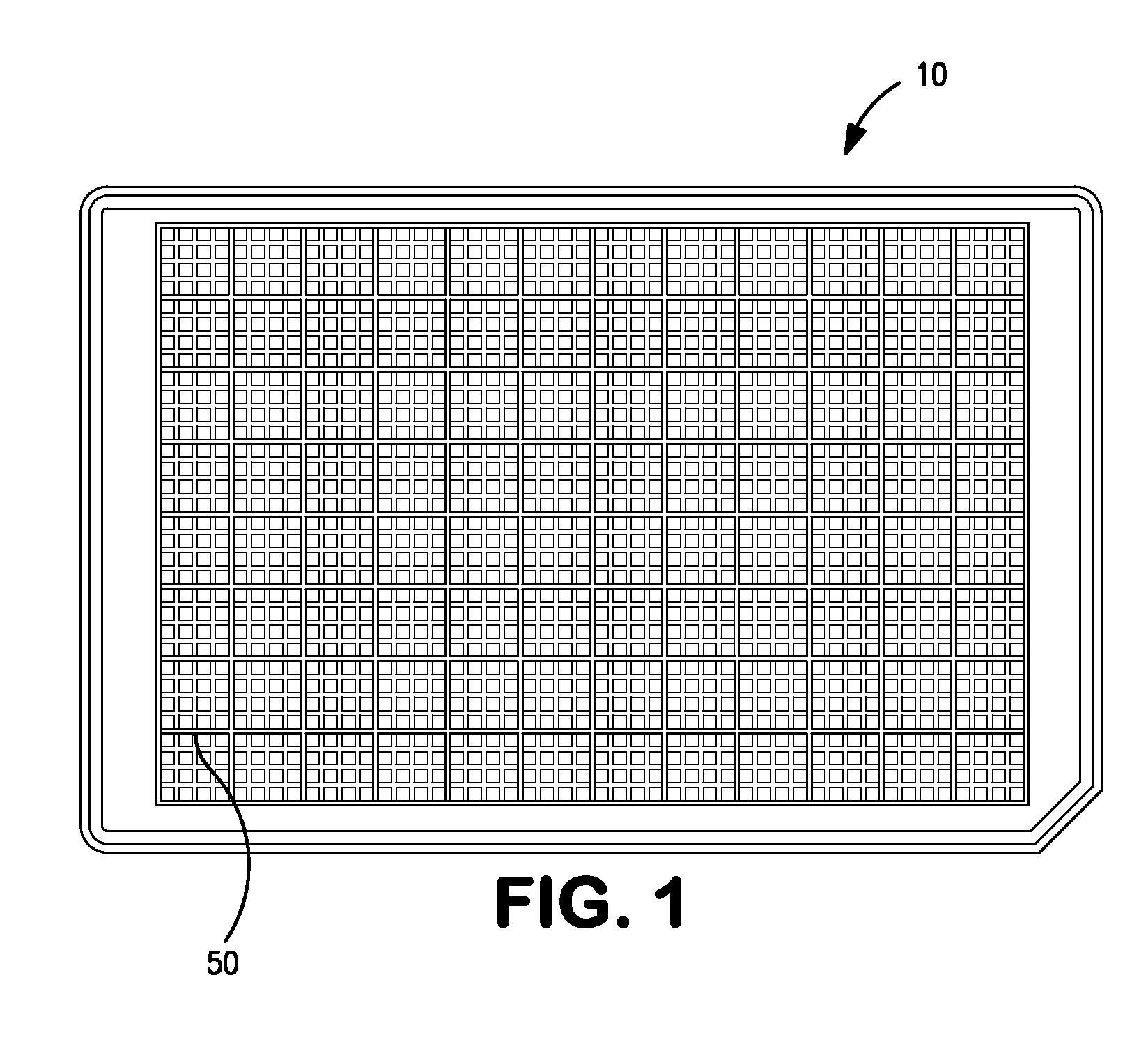
[0015]One embodiment of the present invention relates to a microtiter plate comprising an array of wells, an array of subwells within each of well of the array of wells, a reservoir beneath each array of subwells in fluid communication with all the subwells, and a port in fluid communication with the reservoir beneath each array of subwells. This embodiment may further comprise a lid for the array of wells, wherein the lid contains holes above each subwell and above each port. The well and subwell spacing and dimensions may conform to the SBS standard. The microtiter plate may comprise one or more of polystyrene, polypropylene, high-density polypropylene, low-density polypropylene, a cycloalkene or polycarbonate. In a preferred embodiment the microtiter plate comprises polystyrene.
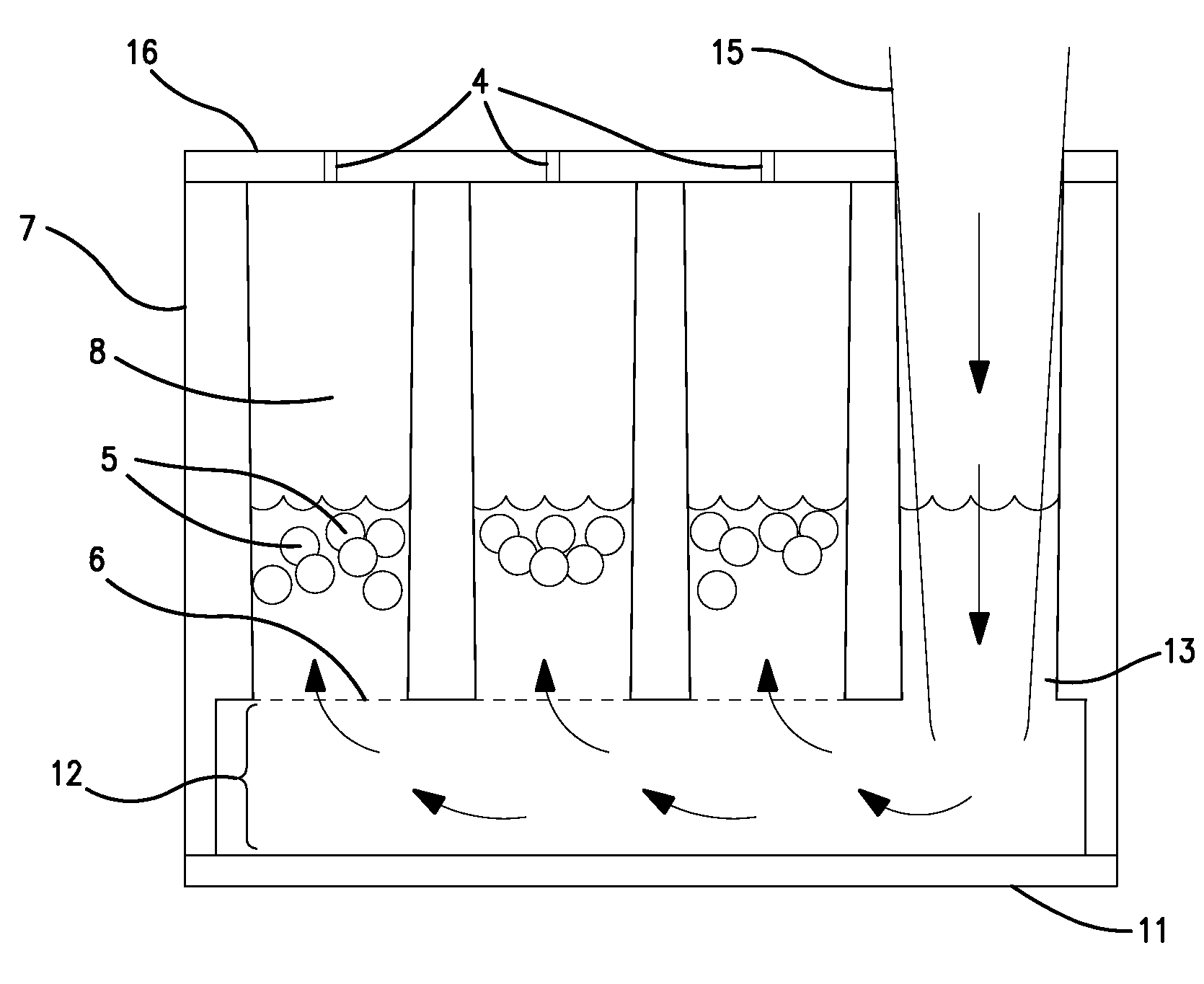
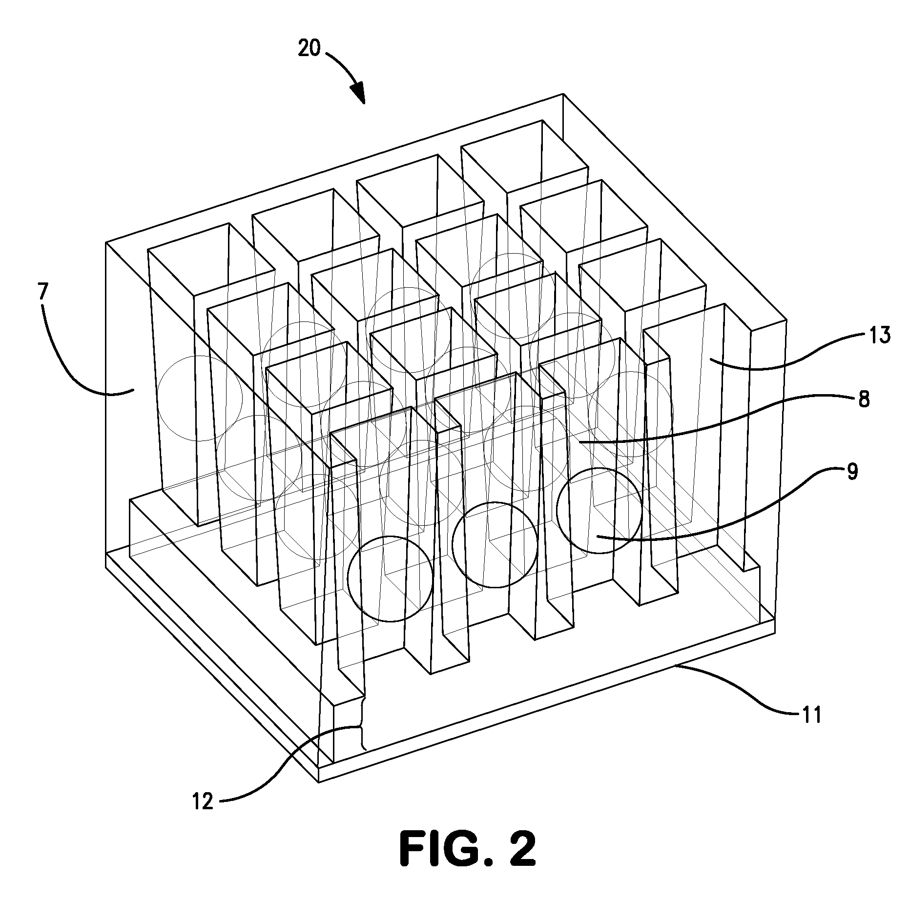
[0016]Another embodiment of the present invention relates to a microtiter plate comprising an array of wells, wherein each well comprises an array of subwells, and wherein the cross-sectional area of the top of each subwell is greater than the cross-sectional area of the bottom of each subwell; a reservoir beneath each array of subwells in fluid communication with the subwells in the array of subwells; and a port within each well, the port being in fluid communication with the reservoir beneath each array of subwells. The tapered shape of the subwell is desirably such that a bead may be retained in the subwell. This embodiment may further comprise a lid for the array of subwells, and the lid may contain openings above each subwell and above each port. The subwells of this embodiment may contain a bead positioned between the top of each subwell and the bottom of each subwell. The spacings and dimensions in the array of wells and the array of subwells in this embodiment may conform to an SBS standard. The microtiter plate of this embodiment may comprise at least one material selected from the group consisting of polystyrene, polypropylene, high-density polypropylene, low-density polypropylene, a cycloalkene or polycarbonate. In a preferred embodiment, the microtiter plate comprises polystyrene. The beads of this embodiment may comprise materials selected from the group consisting of at least one of nylon, polystyrene, stainless steel, glass, agarose, a cellulosic material, or ceramic. The beads of this embodiment may be substantially spherical and have diameters between 0.8 mm and 1.7 mm. The beads of this embodiment may comprise a reagent or reagents for measuring an analyte of interest. The beads of this embodiment may further be positionally indexed within each well.
[0017]A further embodiment of the present invention relates to a microtiter plate comprising an array of wells; an array of subwells within each well; a reservoir beneath the array of subwells, wherein the reservoir is in fluid communication with the array of subwells within a well; a port in fluid communication with the reservoir beneath each array of subwells; and a porous separator positioned between the array of subwells and the reservoir beneath each array of subwells. This embodiment may further comprise a lid for the array of subwells. The lid of this embodiment may contain openings above each subwell and above each port. The subwells of this embodiment may contain one or more beads. The well and subwell spacing and dimensions of this embodiment may conform to an SBS standard. The microtiter plate of this embodiment may comprise one or more of polystyrene, polypropylene, high-density polypropylene, low-density polypropylene, a cycloalkene or polycarbonate. In a preferred embodiment the microtiter plate comprises polystyrene. The beads of this embodiment may comprise a material selected from the group consisting of at least one of nylon, polystyrene, stainless steel, glass, agarose, a cellulosic material or ceramic. The beads of this embodiment may be substantially spherical and have diameters between 0.01 mm and 0.07 mm. Advantageously, the diameter of the beads is greater than the pore size of the porous separator such that the beads are retained within the subwell. The beads of this embodiment may also comprise a reagent or reagents for measuring an analyte of interest. The beads of this embodiment may be positionally indexed within each well.

Problems solved by technology

Use of microtiter plates having, for instance, 1536 wells allow many assays to be done in parallel, but owing to the small size of each well and the complexity of the liquid handling required, it is difficult for these assays to be performed reliably by hand, and robotic systems are almost always used.
This spotting process requires precise targeting during the spotting process and the volume that can be spotted in a defined area is limited.
This method, however, suffers from low throughput, poor data quality and poor reproducibility.
The reading of arrays, however, is difficult in conventional microwells without the use of expensive equipment.
There are also limitations in terms of field of focus and uniform lighting of the bottom of the well using conventional microtiter plates.
In addition, the non-symmetrical design of these plates (solid bottom with open topped wells) results in molded parts that warp due to differential thermal expansion.

Method used


Image

  • System for Preparing Arrays of Biomolecules
  • System for Preparing Arrays of Biomolecules
  • System for Preparing Arrays of Biomolecules

Examples


example 1

Single Analyte Bead Per Subwell

[0039]A microtiter plate 10 which, such as that shown in FIG. 1, is produced such that the walls defining each well 50 have been adapted to form arrays of subwells within each well. A subwell array 20 may be adapted as shown in FIG. 2 such that the horizontal cross-sectional area of each subwell 8 is larger at the top of each subwell 8 than at the bottom of each subwell 8, advantageously without preventing or impeding fluid flow. This allows a spherical analyte bead 9 having an equatorial cross-sectional area between that of the horizontal cross-sectional area of the top and bottom of each subwell 8 to lodge between the top and bottom of each subwell 8. The force required to dislodge the bead 9 is preferably large enough such that the bead 9 will not dislodge under normal shipping and handling conditions. The bead 9 diameter is preferably between 0.8 mm and 1.7 mm and the well 7 and subwell 8 dimensions and spacings conform to the SBS standard. The sub...

example 2

Multiple Analyte Beads Per Subwell

[0042]A microtiter plate 10 such as that shown in FIG. 1 is produced such that the walls defining each well 50 have been adapted to form arrays of subwells 8 within each well 7. A subwell array 20 may be adapted such as that shown in FIG. 4 to include a porous separator 6 between the subwells 8 and a reservoir 12. Each subwell 8 contains multiple analyte beads 5 which are kept in each subwell 8 by the porous separator 6. The porous separator 6 allows the reservoir 12 to remain in fluid contact with each subwell 8.

[0043]Each subwell array 20 further comprises a fluid port 13 which accommodates a liquid handling dispensing tip 15, such as that shown in FIG. 4. The liquid handling dispensing tip 15 preferably is able to access the plate bottom 11 at the bottom of the reservoir 12 such that the liquid handing dispensing tip 15 may fill each subwell 8 in the subwell array 20 simultaneously, as shown by arrows in FIG. 4. Conversely, the liquid handling di...


PUM

PropertyMeasurementUnit
diameteraaaaaaaaaa
diameteraaaaaaaaaa
diameteraaaaaaaaaa

Abstract

Provided are systems for arrays for assaying various biomolecules and other compounds in a microtiter plate format. The wells are designed so as to contain subwells to facilitate fluid communication between subwells and to allow for efficient human or robotic manipulation of samples and assay of binding or other interactions of components within the wells.

Description

CROSS REFERENCE TO RELATED APPLICATIONS[0001]This application claims the benefit of U.S. Provisional Application No. 60 / 970,295, filed Sep. 6, 2007, which application is incorporated by reference in its entirety to the extent there is no inconsistency with the present disclosure.ACKNOWLEDGEMENT OF FEDERAL RESEARCH FUNDING[0002]Not applicable.BACKGROUND OF THE INVENTION[0003]The detection of specific binding between biomolecules, such as antigens, antibodies, the complementary strands of nucleic acid, and ligands and receptors is a key experimental assay in biological research. Given the complexity of biological systems, there is a need for assays that assess the binding of many different potential binding pairs. Assays that provide for rapid, parallel, compact, and inexpensive testing for binding between macromolecules are desired and accelerate discovery of new therapeutic drugs.[0004]High throughput automation has been developed for biomedical and pharmaceutical research. In this ...

Claims


Application Information

Patent Timeline
Patent Type & Authority Applications(United States)
IPC IPC(8): C40B60/14
CPCB01J2219/00315B01J2219/00466B01J2219/005B01L2300/0829B01L3/5025B01L3/5085B01L2200/0642B01J2219/00662
Inventor YU, XIANG
Owner QIAGEN SCIENCES LLC
Why Eureka
Try Eureka