
Dispatch mechanism for dispatching insturctions from a host processor to a co-processor

a technology of a host processor and a dispatch mechanism, which is applied in the field of multi-processor systems, can solve the problems of memory coherence, action will have to be taken to load, and tlb can only maintain a fixed number of mappings

Active Publication Date: 2009-03-12
MICRON TECH INC
View PDF93 Cites 46 Cited by
  • Summary
  • Abstract
  • Description
  • Claims
  • Application Information

AI Technical Summary

Benefits of technology

[0026]According to another embodiment, an entire block of instructions may be stored into the UCB. In this embodiment, one host processor instruction (e.g., an x86 instruction) is included to initiate one cache coherency protocol transaction, which causes the co-processor to begin fetching (loading) the co-processor instructions that were previously placed into the UCB. Thus, the host processor may not be required to perform individual operations for dispatching each instruction individually to the co-processor.

Problems solved by technology

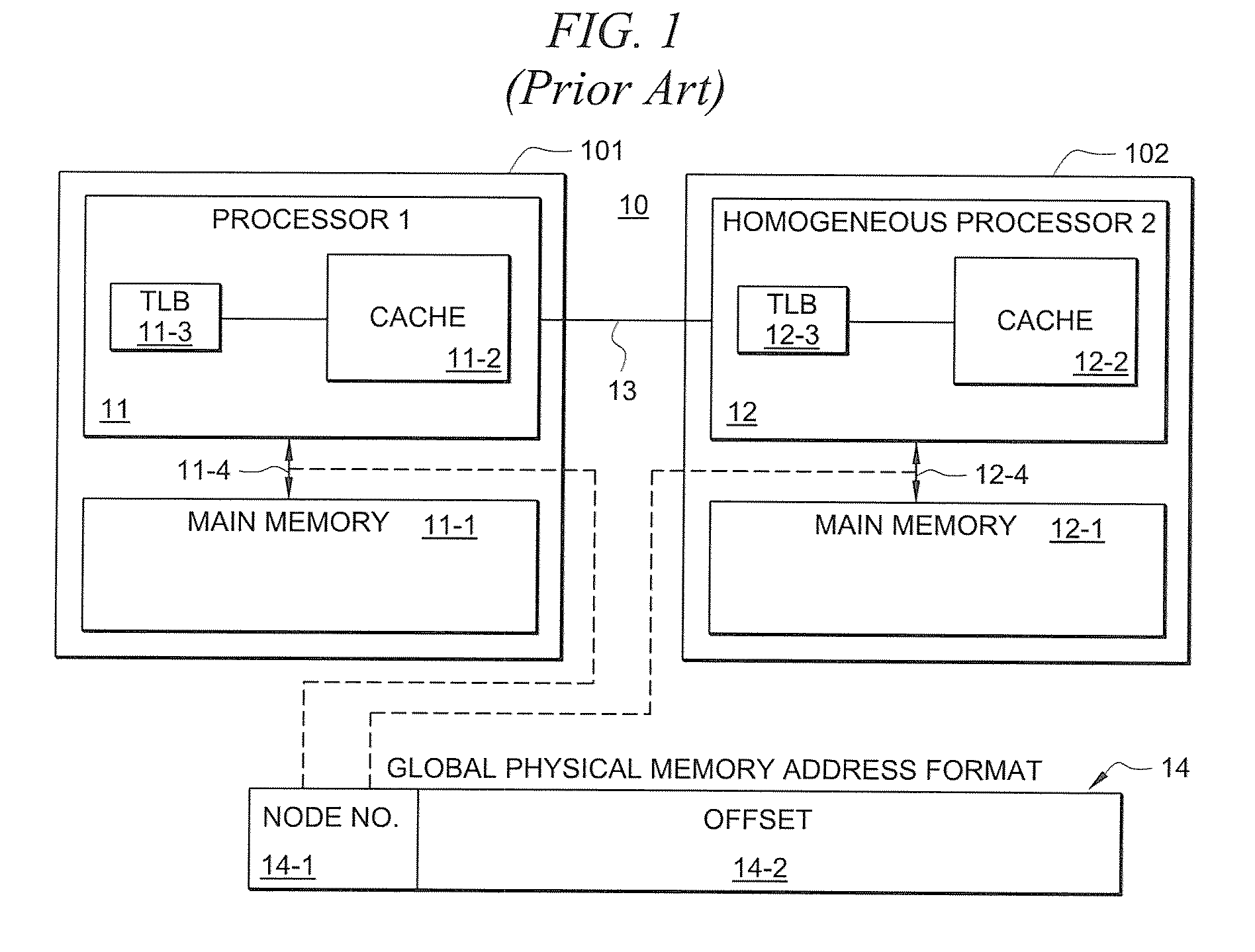
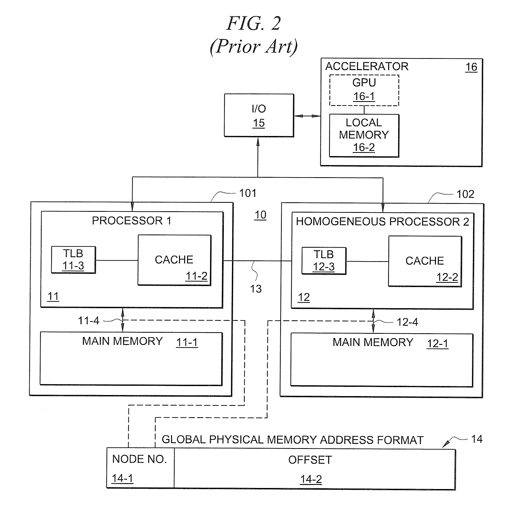
Memory coherency is an issue that affects the design of computer systems in which two or more processors share a common area of memory.
However, the TLB can only maintain a fixed number of mappings between virtual and physical addresses; when the needed translation is not resident in the TLB, action will have to be taken to load it in.
Without a cache coherency mechanism, the programmer must explicitly manage and move data for use by an executable, which lowers programmer productivity and lowers application performance.
However, because the processors are homogeneous, they each have the same processing capabilities, and thus one processor is not better suited for performing certain types of operations more efficiently than the other.
Thus, ASICs are not field-programmable.

Method used


Image

  • Dispatch mechanism for dispatching insturctions from a host processor to a co-processor
  • Dispatch mechanism for dispatching insturctions from a host processor to a co-processor
  • Dispatch mechanism for dispatching insturctions from a host processor to a co-processor

Examples


Embodiment Construction

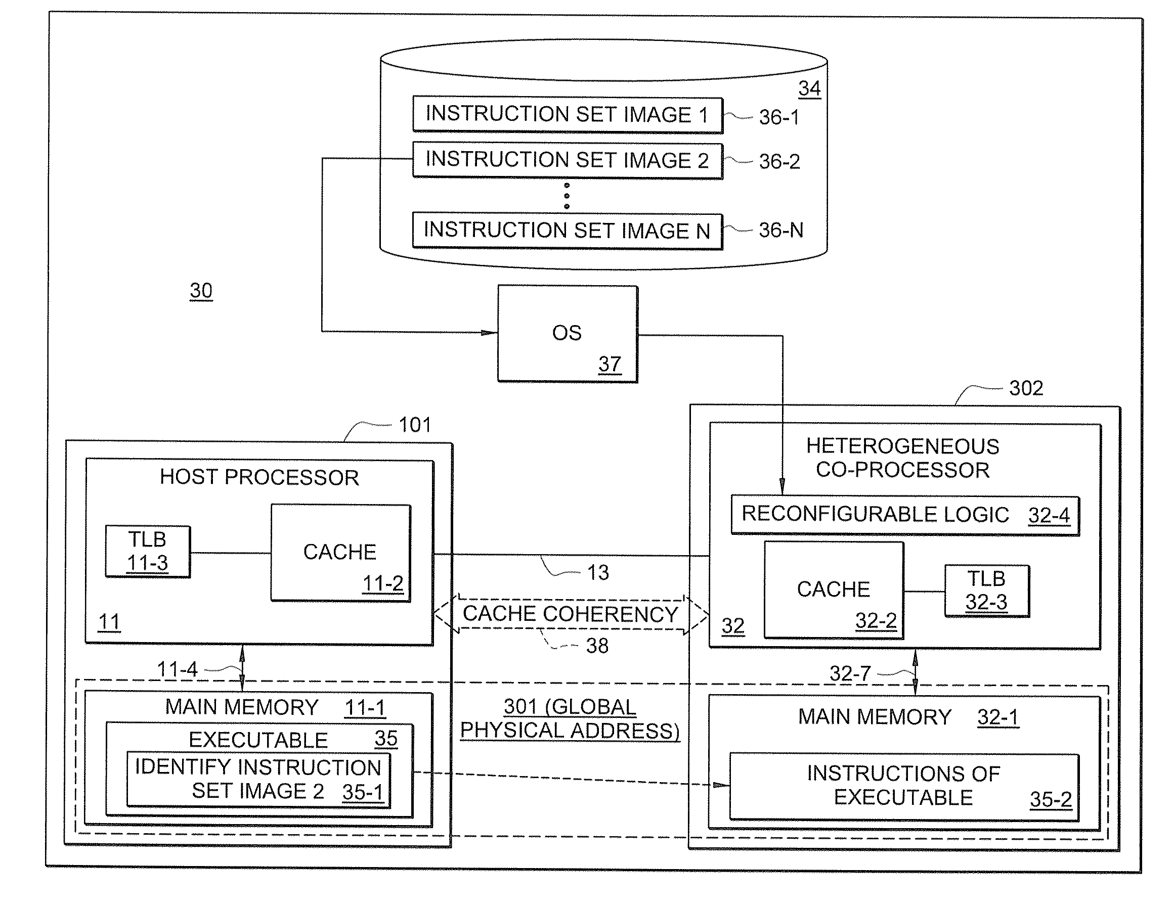
[0060]An exemplary multi-processor system on which the dispatch techniques of embodiments of the present invention may be implemented is first described below, and then exemplary embodiments of such dispatch techniques that may be employed are described. It should be understood that while an exemplary multi-processor system that comprises heterogeneous processors (i.e., having different instruction sets) is described herein, embodiments of dispatch mechanisms / techniques for dispatching instructions of an executable to a heterogeneous co-processor in accordance with the concepts described herein are not limited to the exemplary multi-processor system described.

[0061]FIG. 3 shows an exemplary multi-processor system 30 according to one embodiment of the present invention. As shown, multi-processor system 30 comprises a first node 101 having processor 11, which may be referred to as a “host” processor in this example. In certain embodiments, host processor 11 may comprise a plurality of...


PUM


Abstract

A dispatch mechanism is provided for dispatching instructions of an executable from a host processor to a heterogeneous co-processor. According to certain embodiments, cache coherency is maintained between the host processor and the heterogeneous co-processor, and such cache coherency is leveraged for dispatching instructions of an executable that are to be processed by the co-processor. For instance, in certain embodiments, a designated portion of memory (e.g., “UCB”) is utilized, wherein a host processor may place information in such UCB and the co-processor can retrieve information from the UCB (and vice-versa). The UCB may thus be used to dispatch instructions of an executable for processing by the co-processor. In certain embodiments, the co-processor may comprise dynamically reconfigurable logic which enables the co-processor's instruction set to be dynamically changed, and the dispatching operation may identify one of a plurality of predefined instruction sets to be loaded onto the co-processor.

Description

[0001]The present application relates to the following co-pending and commonly-assigned U.S. patent applications: 1) U.S. patent application Ser. No. 11 / 841,406 (Attorney Docket No. 73225 / P001US / 10709871) filed Aug. 20, 2007 titled “MULTI-PROCESSOR SYSTEM HAVING AT LEAST ONE PROCESSOR THAT COMPRISES A DYNAMICALLY RECONFIGURABLE INSTRUCTION SET”, and 2) U.S. patent application Ser. No. 11 / 847,169 [Attorney Docket No. 73225 / P003US / 10711914] filed Aug. 29, 2007 titled “COMPILER FOR GENERATING AN EXECUTABLE COMPRISING INSTRUCTIONS FOR A PLURALITY OF DIFFERENT INSTRUCTION SETS”, the disclosures of which are hereby incorporated herein by reference.TECHNICAL FIELD[0002]The following description relates generally to multi-processor systems, and more particularly to a dispatch mechanism for dispatching instructions of an executable from a host processor to a heterogeneous co-processor.BACKGROUND OF THE INVENTION[0003]The popularity of computing systems continues to grow and the demand for im...

Claims


Application Information

Patent Timeline
IPC IPC(8): G06F15/76G06F9/02
CPCG06F9/30185G06F9/3802G06F9/3877G06F15/7867G06F9/3897G06F12/0855G06F12/10G06F9/3879
Inventor WALLACH, STEVEN J.BREWER, TONY
Owner MICRON TECH INC
Learn More