Fluid transmission

a transmission device and fluorescence technology, applied in the direction of couplings, dolls, pumping plants, etc., can solve the problems of not being widely used, and being complex, so as to reduce the size of the transmission device and reduce the force or power

Inactive Publication Date: 2009-03-19
HARRIS MARTIN RUSSELL
View PDF7 Cites 31 Cited by
  • Summary
  • Abstract
  • Description
  • Claims
  • Application Information

AI Technical Summary

Benefits of technology

[0015]As with electrostatic motors, the force transmitted by the transmission is proportional to the square of the linear dimensions, that is, the area of the driven section's opposing walls that are pushed apart by the pressurised fluid. Hence, reduction of the size of the transmission by a factor of 10 reduces the force or power by a factor of 100.

Problems solved by technology

Systems that do not require a sliding seal exist (e.g. the pneumatic bellows systems of a pianola) but are not in widespread use.
Electromagnetic linear drives that employ linear motors or leadscrews and piezoelectric linear actuators (e.g. Burleigh inchworm drives) are widely used but are complex.
They are not widely used, however, possibly because they are not easily made.
In particular, the fabrication of small examples can be difficult and ensuring that the seals do not leak can be time consuming.
Currently, the smallest readily available electromagnetic motor is 1.8 mm in diameter and 44 mm long, but costs around AU$1,000 with the required gearbox to produce reasonable torque / force.
However, the amplitudes of the vibrations are ultimately limited by the torque produced by the electrostatic forces—which is small—and are only maximized if the waveform of the drive voltage is applied at the resonant frequency.

Method used


Image

  • Fluid transmission
  • Fluid transmission
  • Fluid transmission

Examples


example

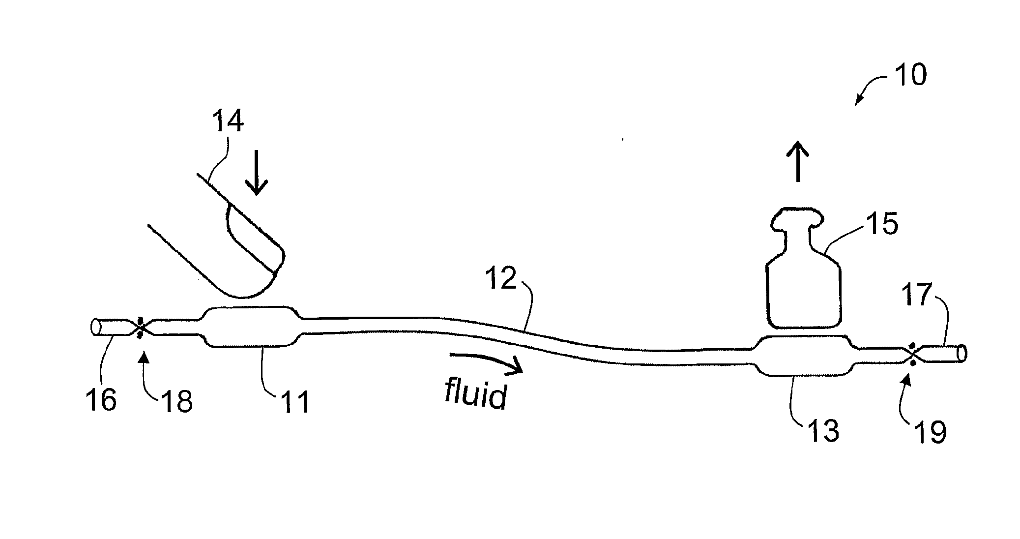
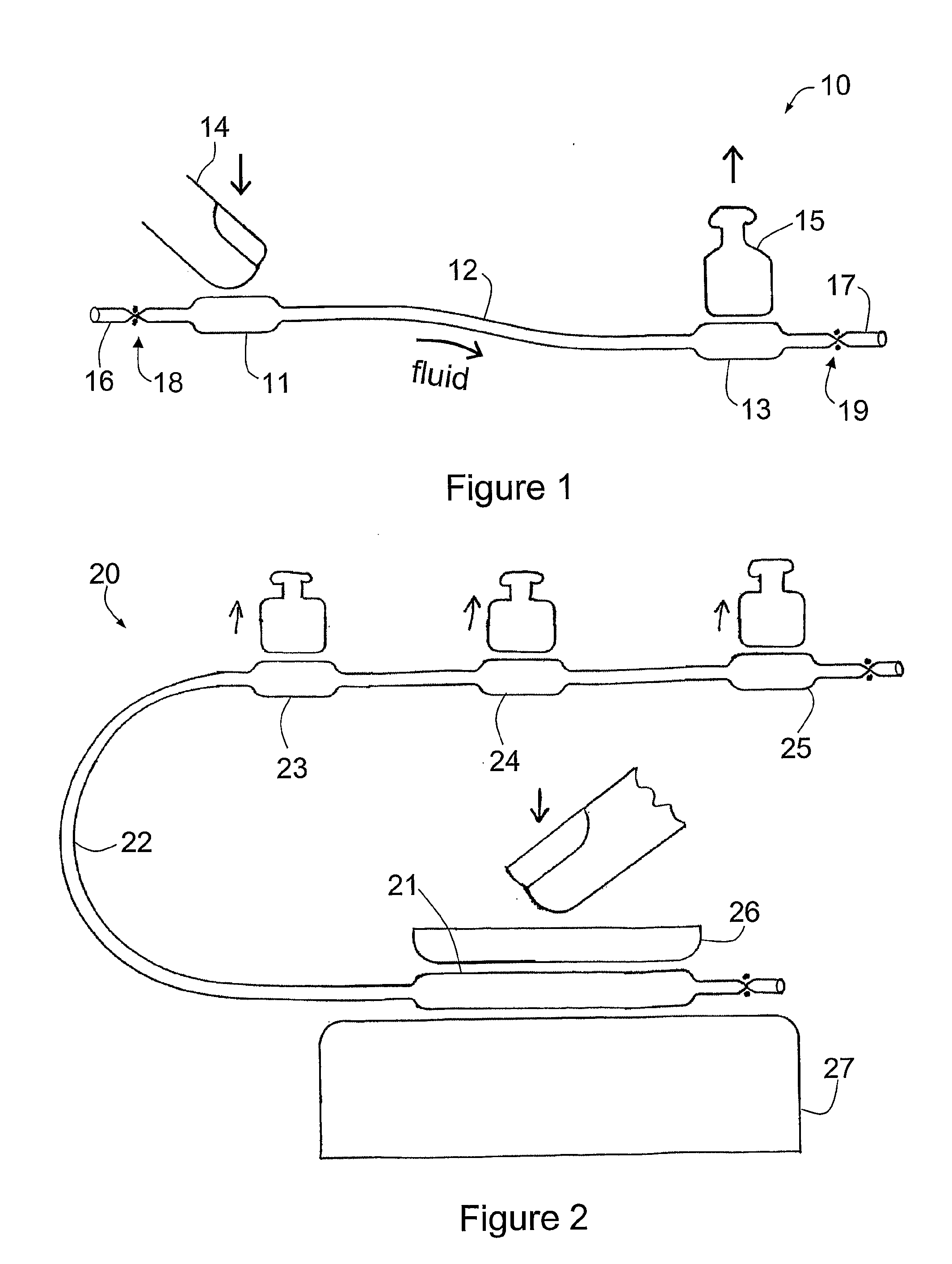
[0105]Experiments were carried out with standard 2 mm diameter heat shrink. A driven bag of dimensions 2.5 mm×8 mm was used to lift a mass of 2 kg, raising it by over 1 mm.

[0106]A more precise set of experiments was carried out using Zeus Sub-Lite-Wall brand PTFE Heat Shrinkable tubing. (PTFE heat shrink tubing remains highly flexible even when shrunk, and can have an external diameter of as little as ˜125 μm when shrunk, so is particularly advantageous in the embodiments described herein.) A driven bag was formed from this material which had the dimensions 0.9 mm×3.0 mm. The driven bag lifted a mass of 120 g to a height of approximately 0.5 mm. The wall thickness of this tube is given by the manufacturer as 0.051 mm. This means that the stroke of this motion is 5 times the collapsed wall thickness, which is very large compared with other miniature actuators such as piezo elements and the like.

[0107]The driven bag was tested with excess pressure to destruction. The irreversible stre...


PUM

PropertyMeasurementUnit
diameteraaaaaaaaaa
diameteraaaaaaaaaa
massaaaaaaaaaa

Abstract

A fluid transmission that employs a fluid to transmit a force, comprising a conduit for the fluid made from heat shrink polymer tubing, wherein at least a portion of the heat shrink polymer tubing is shrunken, whereby the force can be transmitted by the fluid from a first or proximal end of the conduit to a second or distal end of the conduit. Also, an actuator and methods for manufacturing the transmission and actuator.

Description

RELATED APPLICATION[0001]This application is based on and claims the benefit of the filing date of AU application no. 2005904837 filed 2 Sep. 2005, the content of which is incorporated herein by reference in its entirety.FIELD OF THE INVENTION [0002]The present invention relates to a fluid transmission for the transmission of force, of particular use in hydraulic or pneumatic actuators.FIELD OF THE INVENTION [0003]Transmission of an actuating force by the movement of fluid through pipes is employed where smooth and linear motion is required. The most common method uses a cylinder enclosing a piston at the driven end, and a fluid pump (which may also comprise a piston and cylinder) at the driver end.[0004]Pneumatic systems use an actuating fluid in the form of a gas such as air, so leakage of the actuating fluid is a lesser problem than where hydraulic oils are employed. However, hydraulic systems (where the actuating fluid is in the form of a liquid such as water or oil) can produce...

Claims


Application Information

Patent Timeline
Patent Type & Authority Applications(United States)
IPC IPC(8): F15B5/00F15B7/02F15B7/06F15B13/00A63H3/36B29C71/02
CPCA63H3/06A63H13/00F15B15/10F15B7/003A63H29/10Y10T137/86099
Inventor HARRIS, MARTIN RUSSELL
Owner HARRIS MARTIN RUSSELL
Why Eureka
Try Eureka