
Methods for optimizing petroleum reservoir analysis

a petroleum reservoir and optimization technology, applied in the direction of optical radiation measurement, instruments, borehole/well accessories, etc., can solve the problems of adversely affecting the recovery performance, high uncertainty, and adversely affecting the production rate and hydrocarbon recovery

Inactive Publication Date: 2009-03-19
SCHLUMBERGER TECH CORP
View PDF13 Cites 86 Cited by
  • Summary
  • Abstract
  • Description
  • Claims
  • Application Information

AI Technical Summary

Benefits of technology

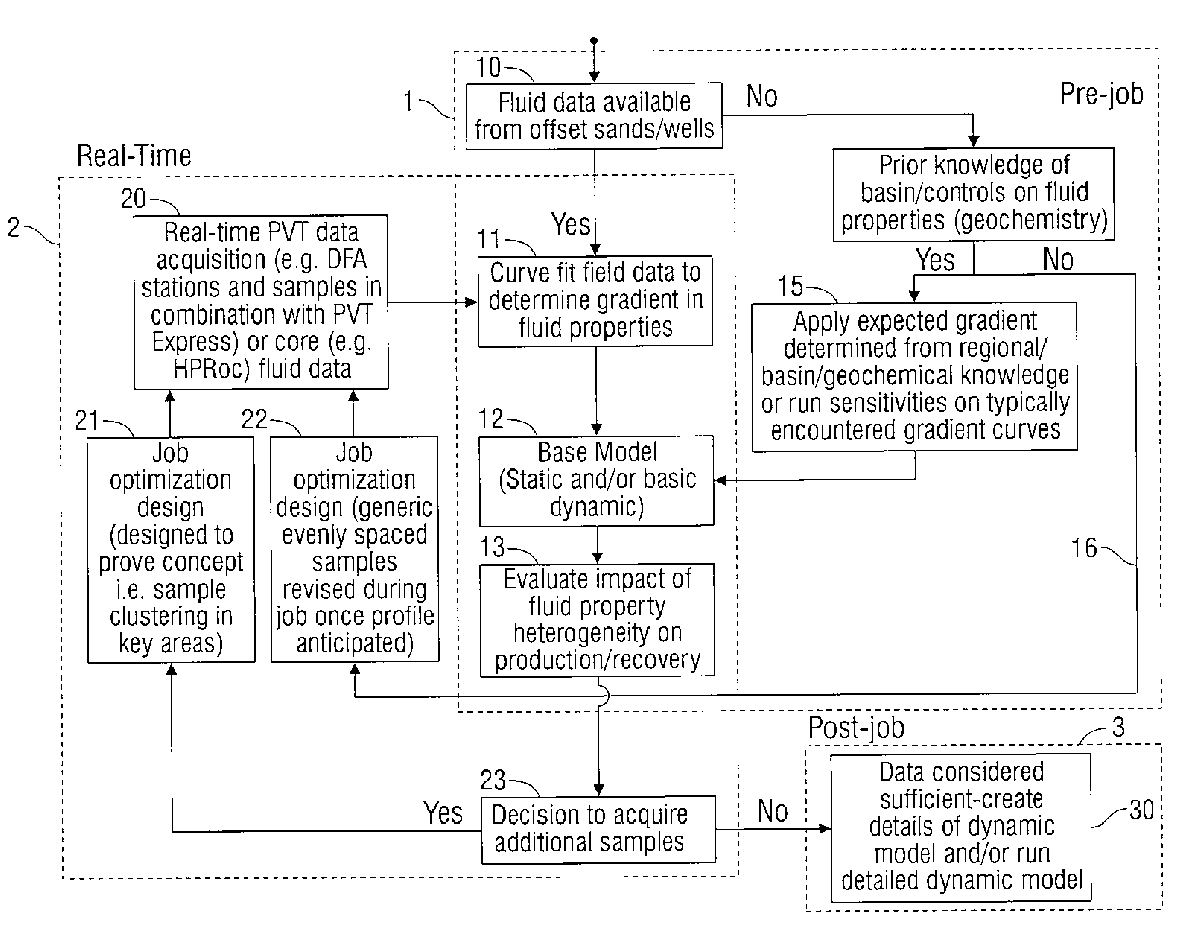
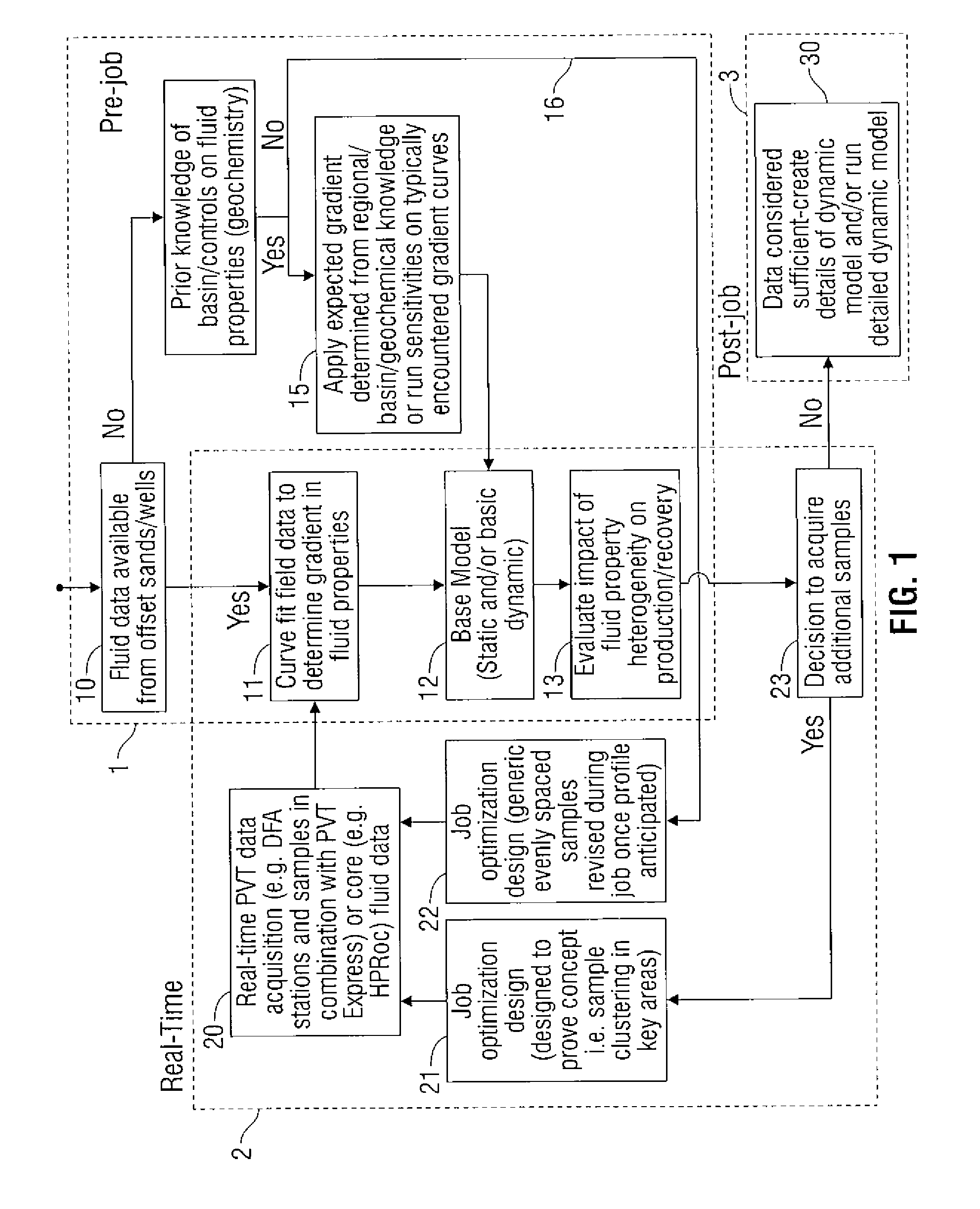
The patent describes methods for better analyzing and sampling petroleum reservoirs, especially when there are differences in fluid properties. These methods can help predict how well the oil will recover from the reservoir. The invention has advantages for studying heavy oil, which can be negatively affected by these differences.

Problems solved by technology

The technical problem addressed in this patent is the need for a better understanding of fluid properties in petroleum reservoirs, particularly when there are gradients in fluid properties due to processes such as organic sources, thermal maturity, and water washing. The current methods used for exploring and developing these reservoirs have high uncertainty, and a new approach is needed to optimize analysis and recovery performance. The patent proposes a method for analyzing fluid properties in real-time, even when there are heterogeneities in the reservoir.

Method used


Image

  • Methods for optimizing petroleum reservoir analysis
  • Methods for optimizing petroleum reservoir analysis

Examples


Embodiment Construction

[0007]Before the present methods are disclosed and described, it is to be understood that the aspects described below are not limited to specific methods, as such may, of course, vary. It is also to be understood that the terminology used herein is for the purpose of describing particular aspects only and is not intended to be limiting.

[0008]In this specification and in the claims that follow, reference will be made to a number of terms that shall be defined to have the following meanings.

[0009]It must be noted that, as used in the specification and the appended claims, the singular forms “a,”“an” and “the” include plural referents unless the context clearly dictates otherwise. Thus, for example, reference to “an oil” includes the combination of two or more different oils, and the like.

[0010]“Optional” or “optionally” means that the subsequently described event or circumstance may or may not occur, and that the description includes instances where the event or circumstance occurs an...


PUM


Abstract

Described herein are methods for optimizing petroleum reservoir analysis and sampling using a real-time component wherein heterogeneities in fluid properties exist. The methods can help predict the recovery performance of oil such as, for example, heavy oil, which can be adversely impacted by fluid property gradients present in the reservoir.

Description


Claims


Application Information

Patent Timeline
Owner SCHLUMBERGER TECH CORP
Learn More