Image forming apparatus including first and second auxiliary residual developer charging features

a technology of image forming apparatus and residual developer, which is applied in the direction of electrographic process apparatus, instrumentation, corona discharge, etc., to achieve the effect of preventing adhesion and improving the recovery performance of transfer residual toner

Inactive Publication Date: 2005-11-08
CANON KK
View PDF9 Cites 14 Cited by
  • Summary
  • Abstract
  • Description
  • Claims
  • Application Information

AI Technical Summary

Benefits of technology

[0025]In view of the above-mentioned problems, an object of the present invention is to provide an image forming apparatus improved in recovery performance of a transfer residual toner at a first auxiliary charging means.
[0026]Another object of the present invention is to prevent adhesion of the transfer residual toner which cannot be recovered by the first auxiliary charging means to a charging means when an amount of the transfer residual toner is increased.
[0027]Another object of the present invention is to prevent an occurrence of a ghost image on an image bearing member.
[0028]Another object of the present invention is to provide an image forming apparatus, capable of forming a multi-color image at a plurality of image forming stations, which can prevent a change in color of a resultant image due to color mixing caused by inclusion of a developer from an upstream-side image forming station into a developing apparatus of a downstream-side image forming station through re-transfer when, e.g., an image having a printing rate on the upstream side in a movement direction of a transfer medium is higher than that on the downstream side.

Problems solved by technology

Accordingly, in order to provide an image forming apparatus with a prolonged life of durability, the recovery container is required to be increased in size, thus being disadvantages in terms of size reduction of the apparatus.
In the cleaner-less-type image forming apparatus wherein the transfer residual toner on the photosensitive member after the transfer process is removed and recovered into the developing apparatus by the simultaneous developing and cleaning method, in the case where the above-mentioned contact charging apparatus is used as the charging apparatus for the photosensitive member, the toner particularly (reversely) charged to a charge polarity opposite to its normal polarity, within the transfer residual toner, attaches to the contact charging apparatus to unacceptably contaminate the contact charging apparatus, thus causing charge failure in same cases.
With respect to the reversed toner or the toner a charge amount of which is not appropriate, the toner cannot removed and recovered into the developing apparatus, thus leading to image failure in some cases.
More specifically, in the case of no first auxiliary charging means, when a transferability o the toner image is poor due to factors, such as a vertical line pattern developer image, environment, the kind of paper (image receiving member), and secondary color portion where a multitude of toner images superposed (e.g., a portion at which a color image of red or orange is formed by disposing yellow and magenta toners in a superposition manner), the amount of the pattern-like image transfer residual toner on the photosensitive member is increased.
As a result, charge failure is caused to occur by contamination of the charging member, or the transfer residual toner image pattern is left to cause an occurrence of its ghost image.
Further, the occurrence of the ghost image for the transfer residual toner image pattern is severely suppressed.
However, in the case of employing the conventional cleaner-less systems, the following problems have arisen.(1) In the case where the image forming apparatus is stopped in such a state that a toner adhered to the photosensitive member due to paper jamming or sudden power failure during image formation is sent to the transfer station, an abnormal image due to charge failure is generated when the following 
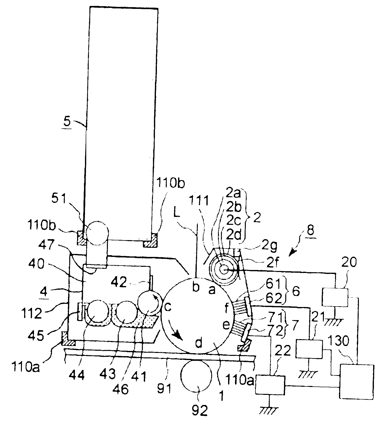
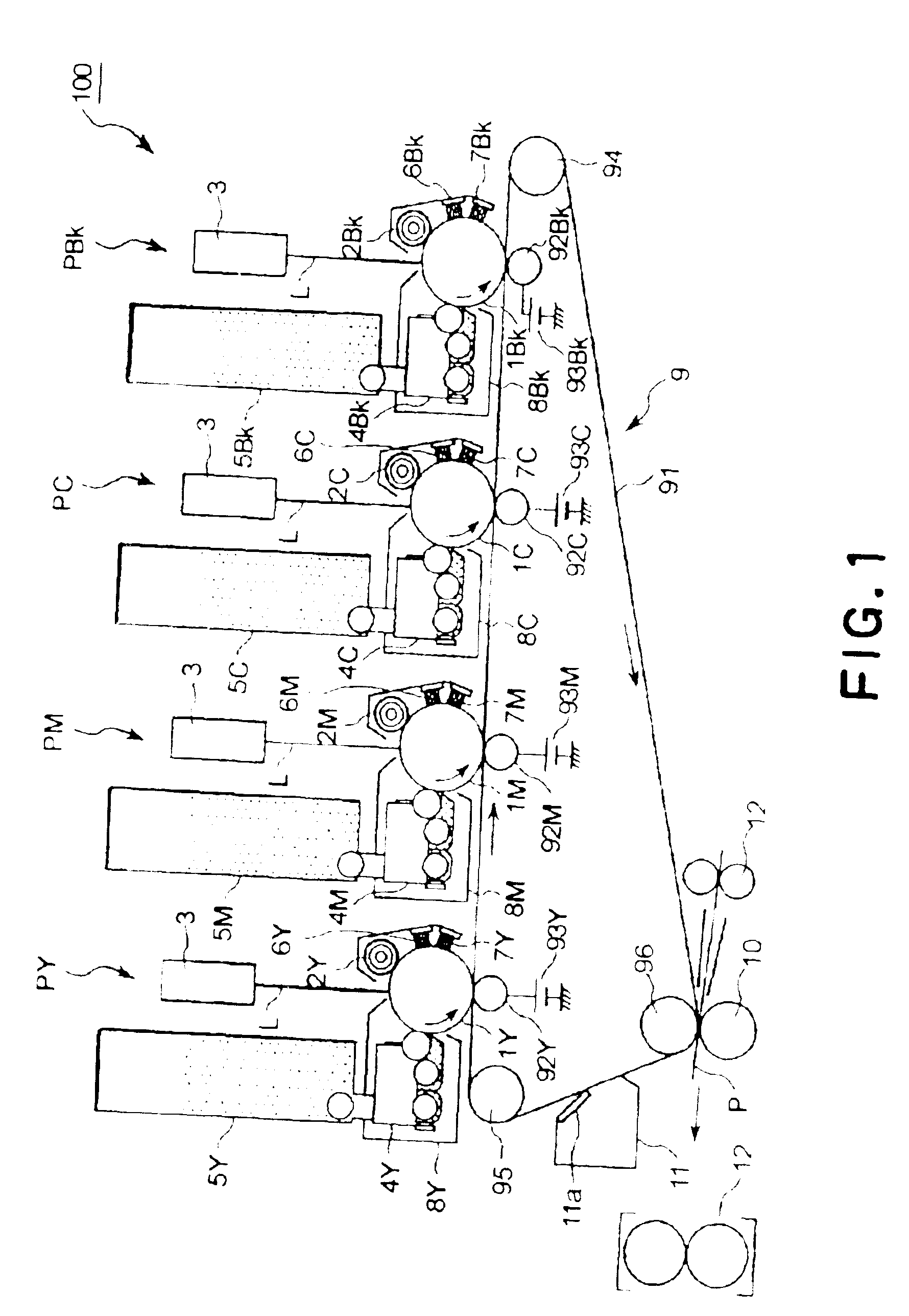
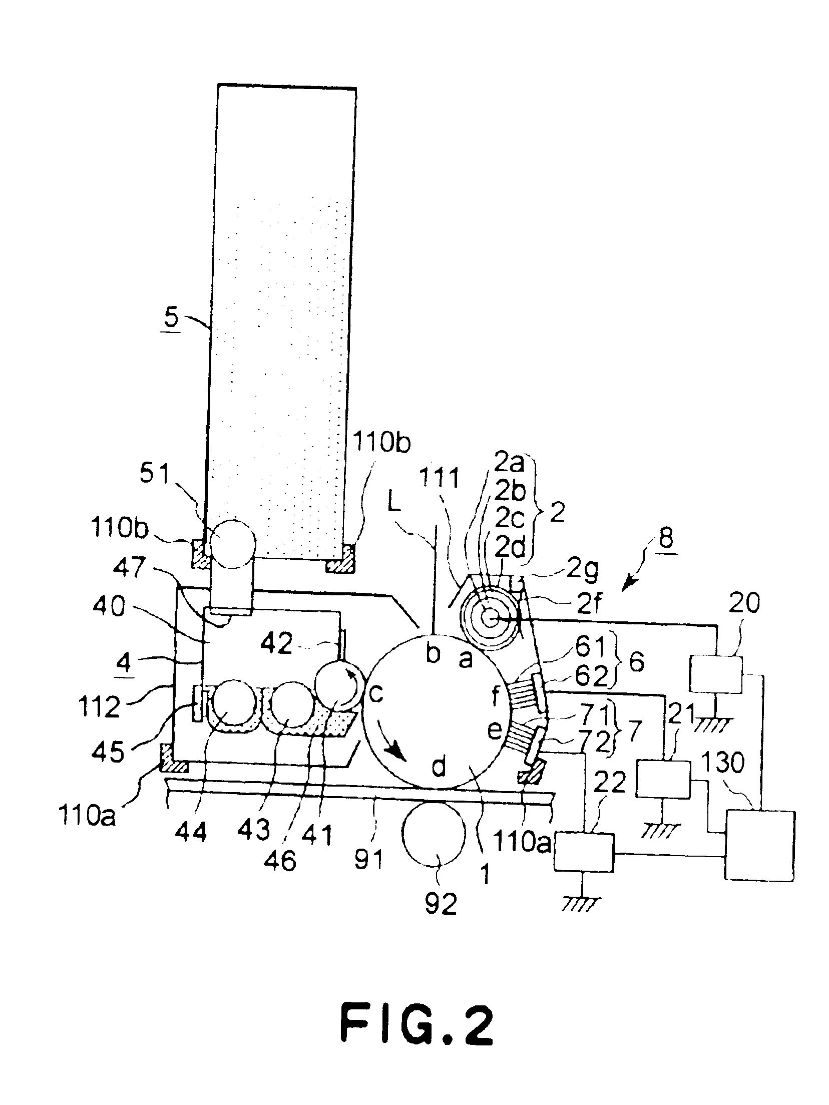
image formation is performed.(2) In the case where a plurality of image forming units (process units) each including a photosensitive member, a developing apparatus, a charging means, a first auxiliary charging means, and a second auxiliary charging means are arranged for image formation of yellow, magenta, cyan and black, and then four color toner images are successively transferred onto an image receiving member, i.e., image formation is performed by a so-called serially-arranged four full-color printers, when a printing operation is performed in such a state that a printing rate of an image forming station located downstream in a movement direction of the image receiving member or the intermediary transfer member (hereinafter, referred to as “downstream station”) is lower than that of an image forming station located upstream in the movement direction (hereinafter, referred to as “upstream station”), the color (hue) at the downstream station is changed.
At this time, an amount of toner after the transfer process is larger than an ordinary amount of the transfer residual toner, so that the charging of the toner layer to the normal polarity by the second auxiliary charging means is performed only at its surface portion due to excessive toner layer thickness even when charge uniformization is performed by the first auxiliary charging means disposed upstream from the second auxiliary charging means in the rotational direction of the photosensitive member, thus failing to be sufficiently performed at a portion of the toner layer closer to the underlying photosensitive member.
As a result, onto the surface of the charging means, the transfer residual toner after passing through the second auxiliary charging means is adhered, thus causing an occurrence of abnormal image due to the charge failure.

Method used


Image

  • Image forming apparatus including first and second auxiliary residual developer charging features
  • Image forming apparatus including first and second auxiliary residual developer charging features
  • Image forming apparatus including first and second auxiliary residual developer charging features

Examples


embodiment 1

(Embodiment 1)

[0034]FIG. 1 shows a schematic sectional view of an embodiment of the image forming apparatus according to the present invention.

[0035]Referring to FIG. 1, an image forming apparatus 100 of this embodiment is a color laser (beam) printer (maximum paper feeding size: A3) using a transfer-type electrophotographic process, a contact charging scheme and a reverse development scheme. Based an image information from an external host connected to a main body of the image forming apparatus so as to be capable of being communicated therewith, a full-color image is formed and outputted onto an image receiving member, such as a sheet, an OHP sheet or cloth.

[0036]The image forming apparatus 100 includes a plurality of process cartridges 8, as image forming station, each comprising an image bearing member, a charging means, a developing means, a first auxiliary charging means, and a second auxiliary charging means. The image forming apparatus 100 is a serially arranged four-drum ty...


PUM


Abstract

An image forming apparatus includes a photosensitive drum, a charge roller for charging the photosensitive drum, a developing device for developing an electrostatic latent image formed on the charged photosensitive drum with a developer, a first auxiliary charging brush which is located upstream from the charge roller in a movement direction of a surface of the photosensitive drum and applies a voltage of a polarity opposite to a normal polarity of a polarity opposite to a normal polarity of the developer, and a second auxiliary charging brush which is located downstream from the first auxiliary charging brush and upstream from the charge roller and applies a voltage of a polarity identical to the normal polarity of the developer. In the image forming apparatus, the first auxiliary charging brush is supplied with an AC voltage to be improved in recovery performance of a transfer residual developer, and contamination of charging means can be prevented.

Description

FIELD OF THE INVENTION AND RELATED ART[0001]The present invention relates to an electro-photographic image forming apparatus, such as a copying machine, a printer or a facsimile machine. More specifically, the present invention relates to an image forming apparatus including an image bearing member; charging means for charging the image bearing member; first auxiliary charging means, for charging a developer on the image bearing member, disposed upstream from the charging means, in a movement direction of a surface of the image bearing member; and second auxiliary charging means, for charging the developer, disposed downstream from the first auxiliary charging means and upstream from the charging means in the movement direction of the surface of the image bearing member.[0002]Conventionally, an image forming apparatus of a transfer type, such as a copying machine, a printer, a facsimile machine, or the like, which employs a transfer type electrophotographic recording system comprise...

Claims


Application Information

Patent Timeline
Patent Type & Authority Patents(United States)
IPC IPC(8): G03G15/08G03G21/00G03G15/02
CPCG03G15/0216G03G2215/021
Inventor KINOSHITA, MASAHIDEOJIMA, MASAKIADACHI, MOTOKIUYAMA, MASAOOKUBO, KAZUHIRO
Owner CANON KK
Why Eureka
Try Eureka