Ink jet recording apparatus

a recording apparatus and jet technology, applied in printing and other directions, can solve the problems of reducing the quality of recorded images, affecting the recovery process, so as to maintain the high recovery performance of the suction recovery process

Inactive Publication Date: 2005-02-03
CANON KK
View PDF14 Cites 14 Cited by
  • Summary
  • Abstract
  • Description
  • Claims
  • Application Information

AI Technical Summary

Benefits of technology

[0015] Ink viscosity when the water or the alcohol completely evaporates from the ink because the apparatus is left in the aforementioned state becomes approximately 300 mPa·s or higher at a normal temperature depending on an ink composition. Needless to say, if a large amount of a highly viscous solvent such as glycerin is used, the viscosity may further exceed the above level to reach 1000 mPa·s or higher. However, even in the case of such a highly viscous ink, as long as a deposit of a dye or urea is not fixed to the discharge opening (nozzle) to cause clogging, it is not impossible to discharge the viscosity-increased ink by applying a very high negative pressure, taking a long time to suck the ink, or keeping the recording head warm before suction to reduce viscosity of the viscosity-increased ink.
[0017] The present invention has been made in view of such a technical problem. It is an object of the invention to provide an ink jet recording apparatus which comprises a pit-in ink supply mechanism, and which can maintain high recovery performance of a suction recovery process if the apparatus is left as it is for a long period of time, and eliminate an inconvenience such as nondischarging or a discharging failure.
[0019] The present invention provides the ink jet recording apparatus which comprises the pit-in ink supply mechanism, and which can maintain high recovery performance of the suction recovery process if the apparatus is left as it is for a long period of time, and eliminate an inconvenience such as nondischarging or a discharging failure.

Problems solved by technology

Consequently, there is an inconvenience that recovery of a discharge opening (or nozzle port) of the recording head is difficult.
However, even in the case of such a highly viscous ink, as long as a deposit of a dye or urea is not fixed to the discharge opening (nozzle) to cause clogging, it is not impossible to discharge the viscosity-increased ink by applying a very high negative pressure, taking a long time to suck the ink, or keeping the recording head warm before suction to reduce viscosity of the viscosity-increased ink.
However, measurement of an ink residual amount in the subtank and investigation as to recovery performance (whether a function of a recovery process is good or bad) after the apparatus is left as it is for a long period of time, have revealed that a great reduction occurs in recovery performance if the ink residual amount exceeds a certain threshold value.
That is, there is a technical problem that if an ink is pit-in supplied from the main tank to the subtank and recording is carried out after a predetermined recovery operation in a state in which the ink jet recording apparatus is left with the ink residual amount set equal to / lower than the threshold value in the subtank and the water or alcohol completely evaporates, nondischarging or a discharging failure may cause a quality reduction in a recorded image.

Method used


Image

  • Ink jet recording apparatus
  • Ink jet recording apparatus
  • Ink jet recording apparatus

Examples


first embodiment

[0062] First, a first embodiment will be described.

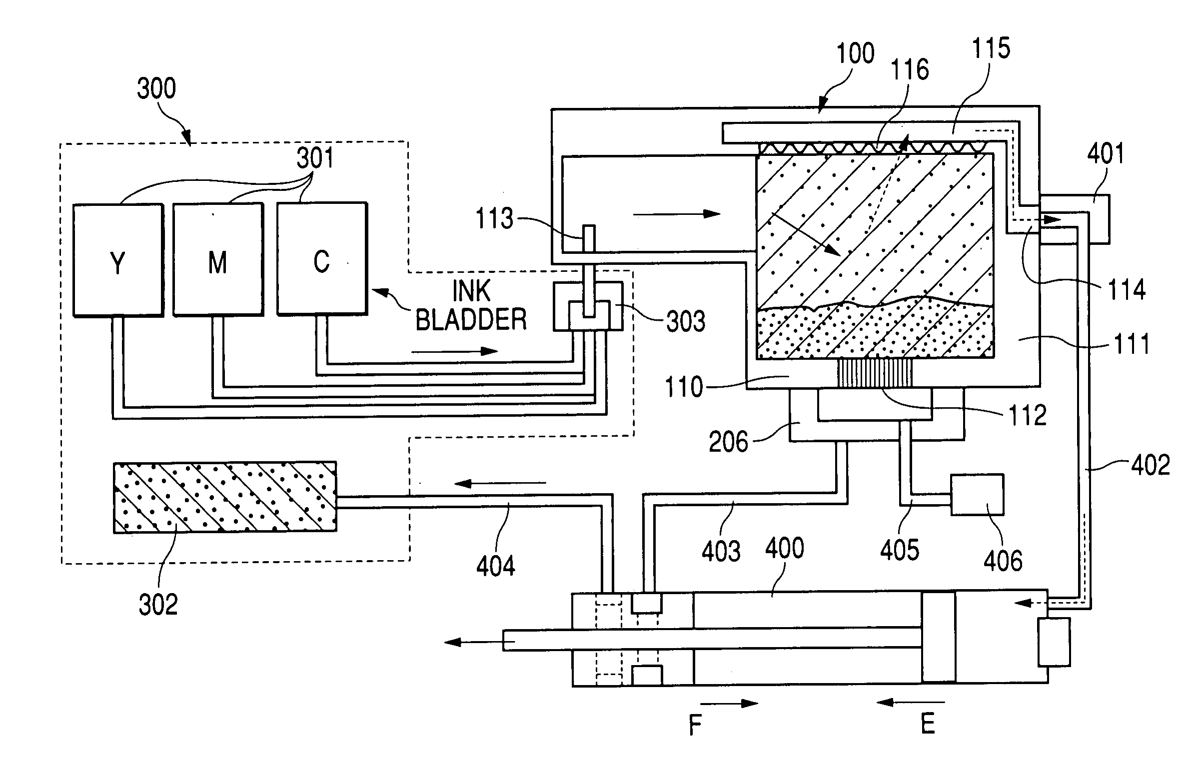
[0063] According to the embodiment, a size (inner volume) of the subtank 111 is defined so that an ink residual amount V in the subtank 111 cab become equal to / higher than a certain threshold value after the end of recording (including printing, image forming, and the like).

[0064] A volume (capacity) of the subtank 111 is preferably made as small as possible in order to install the pit-in ink supply mechanism in the compact recording apparatus. Thus, in the conventional example, a capacity of the subtank 111 is set to 0.3 ml by setting an ink amount likely to be used for recording on one or more largest recording media assumed by the recording apparatus to 0.2 ml, and an ink amount used for a recovery process (suction recovery or the like) to 0.05 ml, and adding 0.05 ml of a margin ink amount.

[0065] Accordingly, if recording of a maximum duty is actually carried out, only 0.05 ml of an ink is left in the subtank 111.

[0066] The in...

second embodiment

[0087] Next, description will be made of a second embodiment which comprises the feature constitution of the present invention.

[0088] According to the second embodiment, by managing an ink residual amount in a subtank, recovery performance is guaranteed after long-time leaving in the subtank smaller than that of the first embodiment.

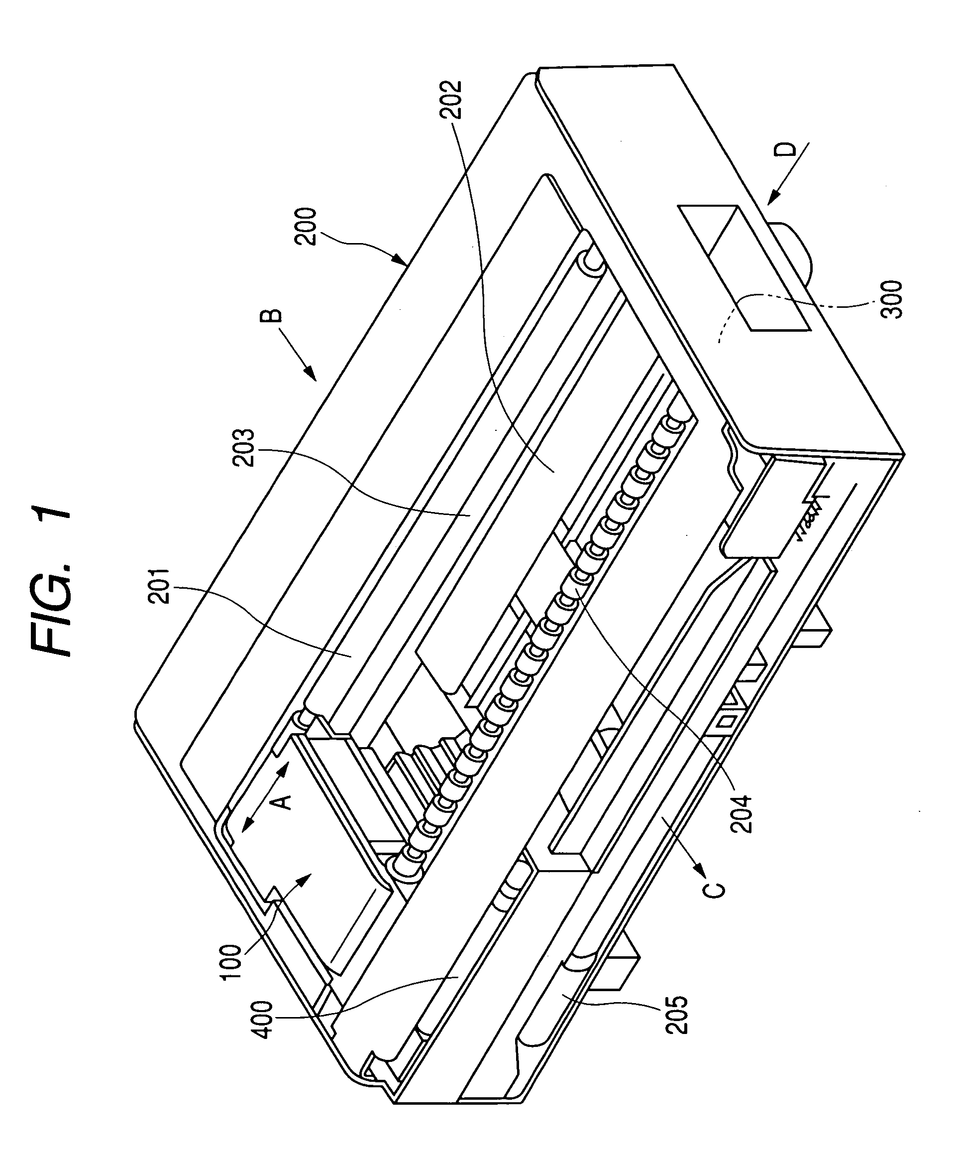
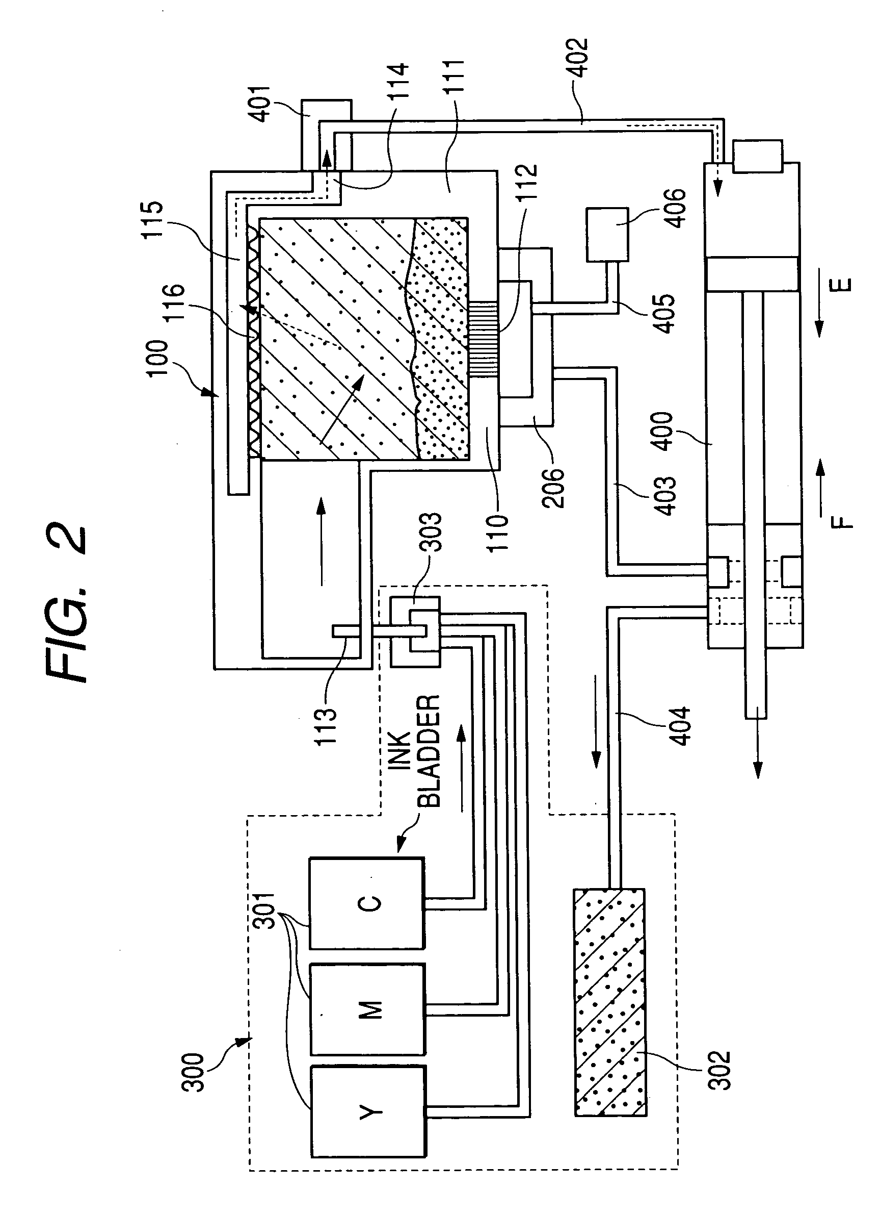
[0089] In the second embodiment, an apparatus main body (FIG. 1), a pit-in ink supply mechanism (FIG. 2), a recording head (FIG. 2), an electric system (FIG. 3), and an ink similar to those of the first embodiment are used unless specified otherwise, and thus detailed description thereof will be omitted.

[0090] According to the embodiment (second embodiment), an ink residual amount in the subtank 111 is managed, a process such as supplying of an ink to the subtank 111 or finishing of recording is carried out when the ink residual amount in the subtank 111 reaches a threshold value equal to that of the first embodiment, and control is executed so that an...

third embodiment

[0102] Next, description will be made of a third embodiment which comprises the feature constitution of the present invention.

[0103] According to the aforementioned second embodiment, only the ink residual amount in the subtank is managed. According to the embodiment (third embodiment), however, an ink concentration in the subtank 111 is managed in addition to the ink residual amount.

[0104] The third embodiment uses an apparatus main body (FIG. 1), a pit-in ink supply mechanism (FIG. 2), a recording head (FIG. 2), an electric system (FIG. 3), and an ink similar to those of the first embodiment unless specified otherwise, and thus detailed description thereof will be omitted.

[0105] According to the third embodiment, a sponge made of a polypropylene (PP) fiber for holding an ink is inserted (fixed) into the subtank 111. Thus, there is an ink which dyes the PP fiber sponge in the subtank 111, and additionally there is an ink stuck or trapped (closed in) in a surface layer, a corner o...


PUM


Abstract

There is disclosed an ink jet recording apparatus which comprises a pit-in ink supply mechanism for interconnecting a main tank and a subtank to be communicated with / separated from each other, and supplying an ink from the subtank to a recording head. In this constitution, an ink residual amount V in the subtank during recording or at the end of recording is selected to be V>v / b in which V is the ink residual amount in the subtank during recording or after the end of recording, b (1>b>0) is a nonvolatile component ratio of the ink, and v is a volume of a liquid chamber of recording means.

Description

[0001] This application claims priority from Japanese Patent Application No. 2003-204079 filed Jul. 30, 2003, which is hereby incorporated by reference herein. BACKGROUND OF THE INVENTION [0002] 1. Field of the Invention [0003] The present invention relates to an ink jet recording apparatus which comprises an ink supply system for replenishing a subtank with an ink from a main tank. [0004] 2. Description of the Related Art [0005] As an ink jet recording apparatus, there has conventionally been used an apparatus of a so-called serial scanning type in which a recording head as recording means and an ink tank as an ink container are replaceably mounted on a carriage movable in a main scanning direction. The ink jet recording apparatus of this type is constituted in such a manner that images are sequentially recorded on a recording medium by repeating main scanning of the carriage on which the recording head and the ink tank are mounted, and subscanning feeding of the recording medium s...

Claims


Application Information

Patent Timeline
Patent Type & Authority Applications(United States)
IPC IPC(8): B41J2/165B41J2/175
CPCB41J2/17509B41J2002/17569B41J2/17566
Inventor MIZOGUCHI, YOSHITO
Owner CANON KK
Why Eureka
Try Eureka