Method for shifting actuation of an automated transmission

Active Publication Date: 2009-03-19
ZF FRIEDRICHSHAFEN AG
View PDF12 Cites 20 Cited by
  • Summary
  • Abstract
  • Description
  • Claims
  • Application Information

AI Technical Summary

Benefits of technology

[0031]During the load reduction of the prime mover in the momentary first method step SH1 or SR1, the separating clutch K is advantageously partly disengaged already up to above the slip limit. Hereby the separating clutch K can be consecutively disengaged faster since then no more waiting time results for the prior filling of the clutch actuator with a pressure means and for bypassing an idle path of the clutch actuation device.
[0032]During activation of the target ratio stage G1, G1′ or G3, G4′ of the main transmission HG, HG′, that is, in the method step SH7 or SR4a, and/or during activation of the target ratio stage S or L of the range change group GP, that is, in the method step SH4 or SR6, if the existence of a tooth-on-tooth position on the dog clutch concerned is found, then the shifting sequence, while maintaining the engagement control force concerned, is conveniently continued, inasmuch as the tooth-on-tooth position is canceled by a relative rotation, which necessarily occurs subsequently, of the transmission shaft (WVG1, WH; WVG, WH; WH, WGA) and the dog clutch can then be engaged without delay of the shifting sequence.
[0

Problems solved by technology

But since in a group transmission many gearshifts require the change of ratio stages in many parts and thus the sequence is relatively complicated, most group transmissions known are designed either partly automated or fully automatedly shiftable.
But since the concerned synchronized separating clutches, due to a complicated construction, are comparatively expensive and require a relatively large space and, due to wear, the lifetime

Method used


Image

  • Method for shifting actuation of an automated transmission
  • Method for shifting actuation of an automated transmission
  • Method for shifting actuation of an automated transmission

Examples


Example

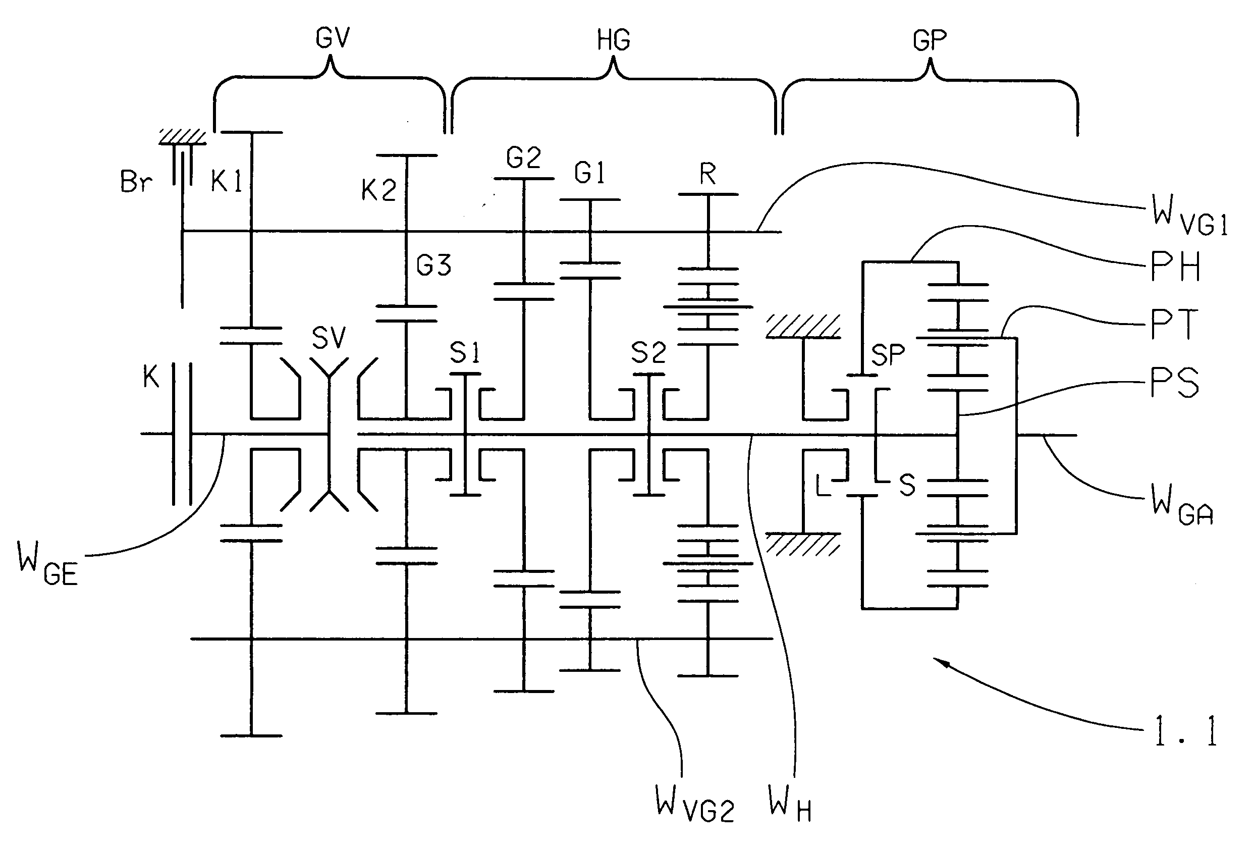
[0040]In FIG. 3 is shown a group transmission 1.1 where the inventive method can be used. The group transmission 1.1 comprises one main transmission HG, one group GV front-mounted thereon by drive technology and one range change group GP rear-mounted on the main transmission HG and which in its function technical construction extensively corresponds to an embodiment of a group transmission known per se of the AS-Traonic series.

[0041]The main transmission HG is constructed in countershaft design and has one main shaft WH and two countershafts WVG1 and WVG2 wherein the first countershaft WVG1 is coupled with an actuatable transmission brake Br. The main transmission HG is designed with three ratio stages G1, G2, G3 for the forward movement and one ratio stage R for the reverse drive. The idler gears of the ratio stages G1, G2, R are each rotatably placed upon the main shaft WH and are shiftable by way of coordinated dog clutches. The coordinated fixed gears are non-rotatably situated ...


PUM


Abstract

A method for shifting an automated transmission situated in a drive train of a motor vehicle between an engine and a drive axle and having at least one multi-speed main transmission and a two-speed range change group rear-mounted thereon. The main transmission has at least one counter-shaft with an transmission brake. A clutch engages the prime mover and the main transmission and the range change group is shifted via unsynchronized dog clutches, which are combined in pairs in a common shift set having two shift positions and one neutral position such that during a range change gearshift, both in the main transmission and in the range change group, a change between two ratio stages occurs. A range change up-shift and down-shift each include active synchronization of the dog clutch by way of the transmission brake and of the separating clutch.

Description

[0001]This application claims priority from German Application Serial No. 10 2007 043 694.9 filed Sep. 15, 2007.FIELD OF THE INVENTION[0002]The invention concerns a method for shifting actuation of an automated group transmission situated in a drive train of a motor vehicle between a prime mover and an axle drive and comprising at least one multi-speed main transmission and one two-speed range change group rear-mounted thereon, and in which the main transmission is constructed in countershaft design having at least one countershaft provided with an actuatable transmission brake, the input shaft is connected with the prime mover, via an actuatable separating clutch and the main transmission, the same as the range change group, are each actuatable via unsynchronized dog clutches combined in pairs in a common gearset having two shift positions and one neutral position wherein, during a range change gearshift both in the main transmission and in the range change group a shift occurs bet...

Claims


Application Information

Patent Timeline
IPC IPC(8): F16H59/04F16H59/08
CPCF16H61/0403F16H61/08F16H61/702F16H63/502Y10T74/19251F16H2306/42F16H2306/48Y10T477/6407F16H2061/0411
Inventor BADER, JOSEFGRAF, ANDREASMILLER, MARTINSTEINBORN, MARIOHAFEN, THOMAS
Owner ZF FRIEDRICHSHAFEN AG
Why Eureka
Try Eureka