Eureka AIR delivers breakthrough ideas for toughest innovation challenges, trusted by R&D personnel around the world.

Shift control method for an automated range-change transmission

Active Publication Date: 2018-05-24
ZF FRIEDRICHSHAFEN AG
View PDF48 Cites 0 Cited by
  • Summary
  • Abstract
  • Description
  • Claims
  • Application Information

AI Technical Summary

Benefits of technology

The present invention proposes a novel process for shifting the auxiliary transmission of an automated vehicle, which improves the service life of the synchronized clutches of the front-mounted group and reduces the number of gear ratio changes. The process only shifts gears when necessary, such as when the accelerator pedal is pressed, which results in a gear change with a small transmission ratio increment. This reduces wear and tear on the synchronization devices of the front-mounted group and improves overall driving performance. A control unit and computer program product for performing this process are also provided.

Problems solved by technology

However, as many gear changes in an auxiliary transmission entail changes of transmission ratio steps in several subtransmissions, making them rather complex, most of the known auxiliary transmissions are designed to be shiftable in either a partially automated or fully automated manner.

Method used


Image

  • Shift control method for an automated range-change transmission
  • Shift control method for an automated range-change transmission
  • Shift control method for an automated range-change transmission

Examples


Embodiment Construction

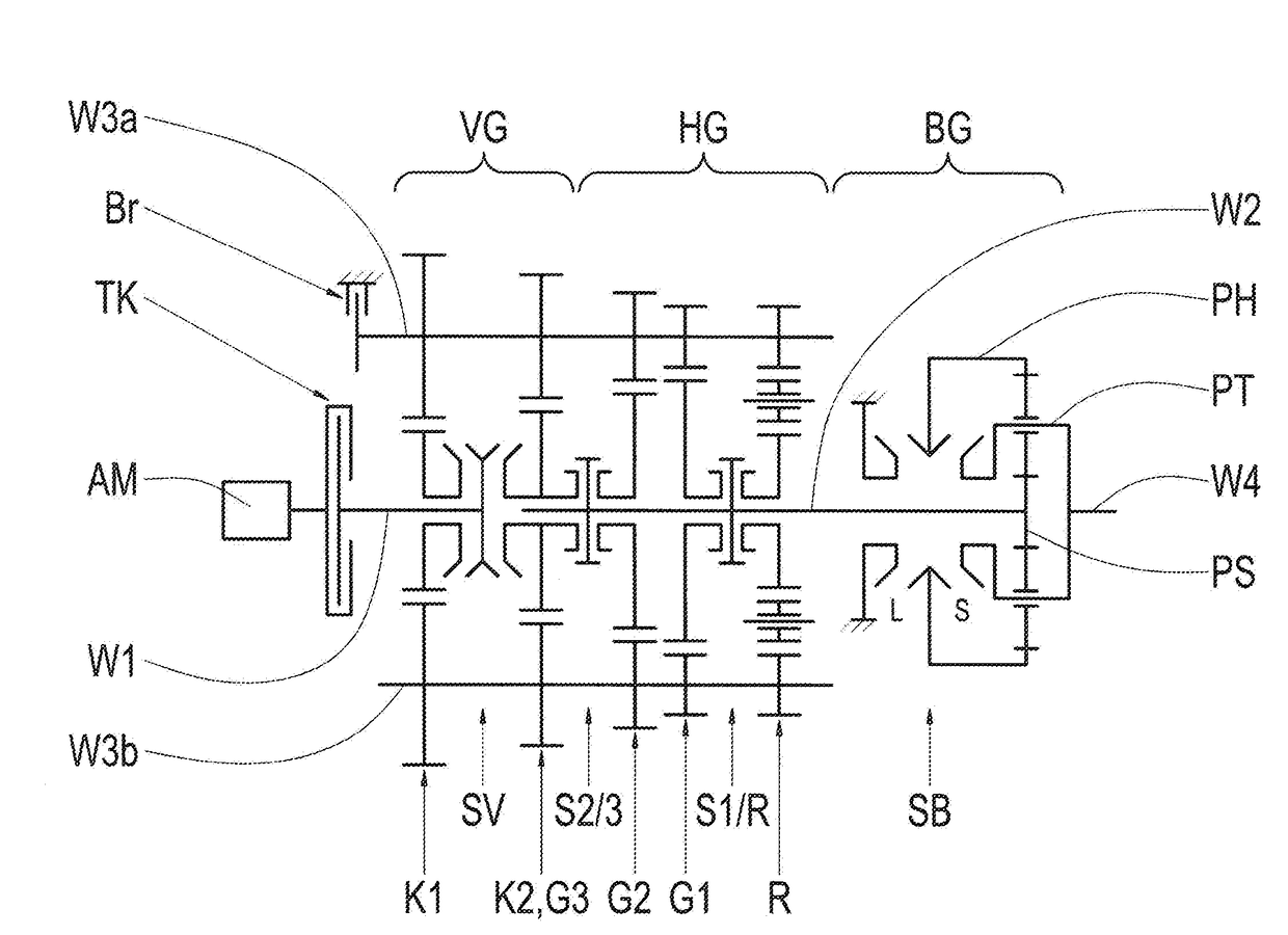
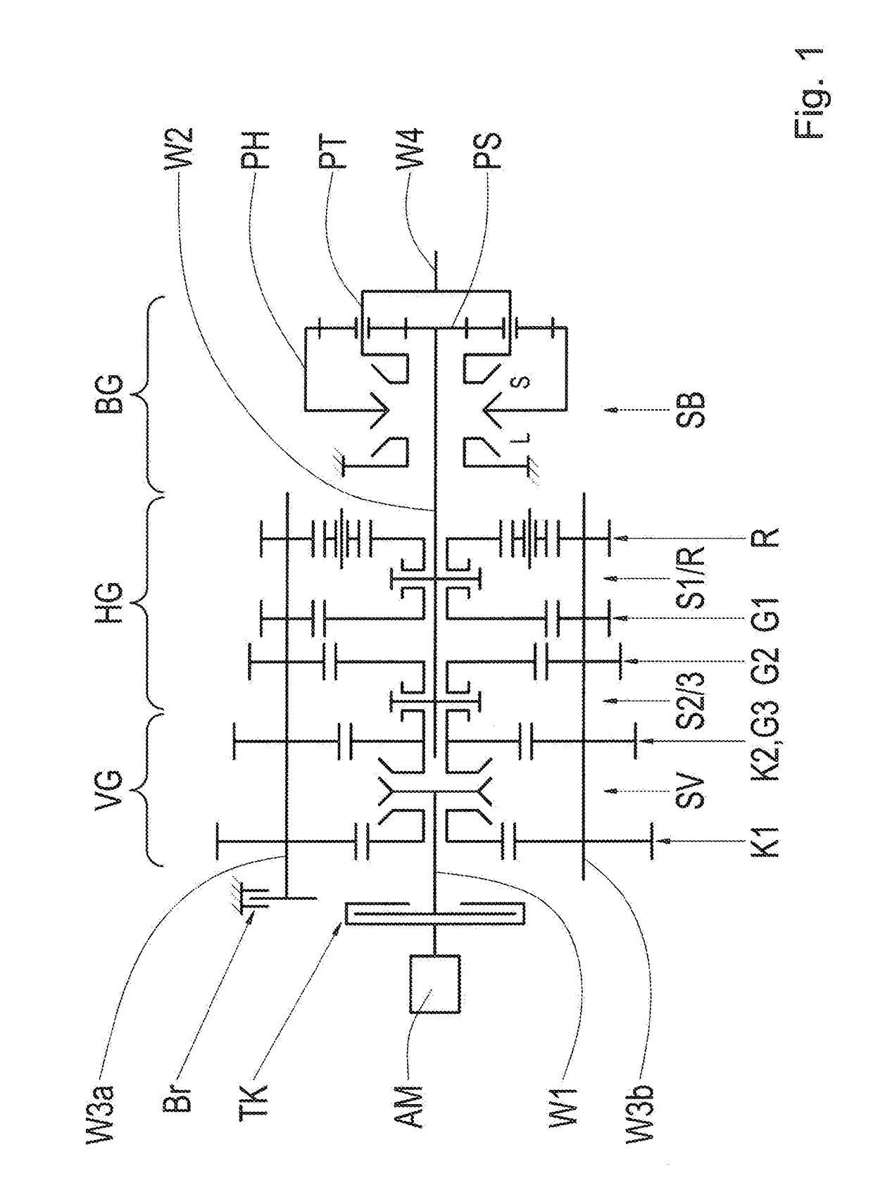
[0032]The auxiliary transmission depicted in FIG. 1 comprises a three-stage main gearing HG, a front-mounted group, or splitter group VG connected upstream of the main gearing HG on the drive train, and a range group BG downstream of the main gearing HG. The main gearing HG of the auxiliary transmission is configured here as a direct gear transmission in a countershaft design and has a main shaft W2 and two countershafts W3a and W3b, wherein the first countershaft W3a is equipped with a controllable transmission brake Br.

[0033]The main gearing HG has a three-step configuration, with three transmission ratio steps G1, G2, G3 for forward driving and one transmission ratio step R for driving in reverse. Idler gears of the transmission ratio steps G1, G2 and R are each rotatably supported on the main shaft W2, and can be shifted via dedicated clutches. The dedicated fixed gears are arranged on the countershafts W3a and W3b in a rotationally fixed manner.

[0034]The highest transmission ra...


PUM


Abstract

A method for shift control of an automated auxiliary transmission that is mounted in a drive train of a motor vehicle between a drive motor (AM) and a final drive, and includes at least one multi-step main gearing (HG) and one two-step front-mounted group (VG) connected upstream of the main gearing (HG), and with which the main gearing (HG) can be shifted via unsynchronized clutches and the front-mounted group can be shifted via synchronized clutches. Depending on the currently existing driving or operating situation, a gear change is performed in the auxiliary transmission through a change in the transmission ratio step (G1, G2, G3) of the main gearing (HG) while maintaining the currently engaged transmission ratio step (K1, K2) in the front-mounted group (VG).

Description

[0001]This application claims priority from German patent application serial no. 10 2016 223 016.6 filed Nov. 22, 2016.FIELD OF THE INVENTION[0002]The present invention relates to a process for the shift control of an automated auxiliary transmission that is mounted in a drive train of a motor vehicle between a drive motor and a final drive and comprises at least one multi-stage main gearing and a two-stage front-mounted group upstream of the main gearing. Moreover, the invention relates to a control unit, which is configured for performing the process, and a matching computer program product.BACKGROUND OF THE INVENTION[0003]Auxiliary transmissions having a multi-stage main gearing and a front-mounted group, upstream thereof on the drive train, and a range group, downstream thereof on the drive train, have been known for some time and are preferably used in commercial vehicles. Due to the front-mounted group, usually having a two-stage design and a small transmission ratio increment...

Claims


Application Information

Patent Timeline
IPC IPC(8): F16H63/50B60W10/06B60W10/11
CPCF16H63/502B60W10/06B60W10/11B60W30/19F16H61/0403F16H2306/48F16H61/02F16H61/70F16H63/44F16H2200/0069F16H61/702F16H2061/085F16H37/046
Inventor STEINBORN, MARIOMAYERHOFER, TOBIAS
Owner ZF FRIEDRICHSHAFEN AG
Why Eureka
Eureka Blog
Learn More