Eureka AIR delivers breakthrough ideas for toughest innovation challenges, trusted by R&D personnel around the world.

Gearbox for a vehicle and vehicle, comprising such a gearbox

Active Publication Date: 2017-03-30
SCANIA CV AB
View PDF4 Cites 8 Cited by
  • Summary
  • Abstract
  • Description
  • Claims
  • Application Information

AI Technical Summary

Benefits of technology

The present invention aims to provide a gearbox with several technical effects. Firstly, it eliminates the disadvantages of a reverse gear in the main gearbox. Secondly, it allows for short shifting times. Thirdly, it is highly reliable and secure, with efficient use of all component parts. Fourthly, it reduces fuel consumption and noise from the gearbox. Finally, it is easy to repair.

Problems solved by technology

The ring gear's freedom of movement in an axial direction is limited by the geometrical design of the teeth of the ring gear and the coupling ring.
These synchronisation devices are, however, subjected to wear and result in considerable costs of repair.
If the range gearbox transfers large torques, the synchronisation devices will have considerable dimensions, entailing increased weight, increased space requirement and increased moment of inertia.
When the high range position is connected, the torque will be transferred from the sun wheel to the planetary wheels, entailing that facets may form on the cog flanks of the sun wheel, which creates noise in the gearbox and accelerates wear of the planetary gear's cogwheels.
The cogwheel, which is intended for the reverse gear, entails an extension of the main gearbox and an undesired weight increase of the vehicle.
The cogwheel rotates in the opposite direction to other cogwheels in the main gearbox, which entails losses.
Said cogwheel intended for the reverse gear often has a tendency to induce unwanted rattle in the transmission, arising from an intermediate cogwheel, arranged between a countershaft and the main shaft in the main gearbox.
Prior art gearboxes must often be completely dismantled when a component is replaced, which means that it takes a lot of time and that it is costly to repair the gearbox.

Method used


Image

  • Gearbox for a vehicle and vehicle, comprising such a gearbox
  • Gearbox for a vehicle and vehicle, comprising such a gearbox
  • Gearbox for a vehicle and vehicle, comprising such a gearbox

Examples


Embodiment Construction

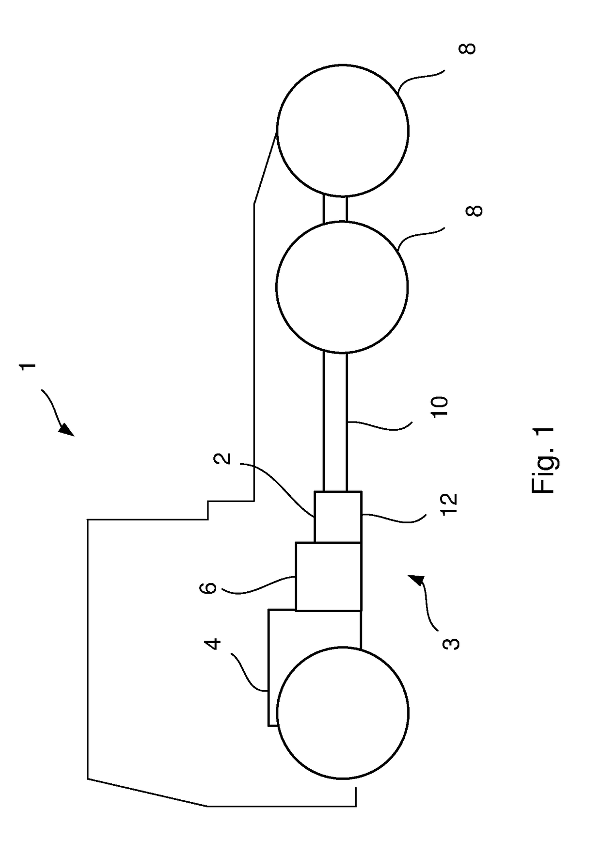
[0048]FIG. 1 shows a side view of a vehicle 1, e.g. a truck, which comprises a gearbox 2 according to the present invention. The gearbox 2 is comprised in a transmission 3, which comprises a combustion engine 4, a main gearbox 6 and a propeller shaft 10. The combustion engine 4 is connected to a main gearbox 6, which in turn is connected to the gearbox 2 according to the present invention. The gearbox 2 is also connected to the driving wheels 8 of the vehicle 1, via the propeller shaft 10. The gearbox 2 according to the present invention is also called a range gearbox, and its objective is to double the number of gearing possibilities. The gearbox 2 is surrounded by a gearbox housing 12.

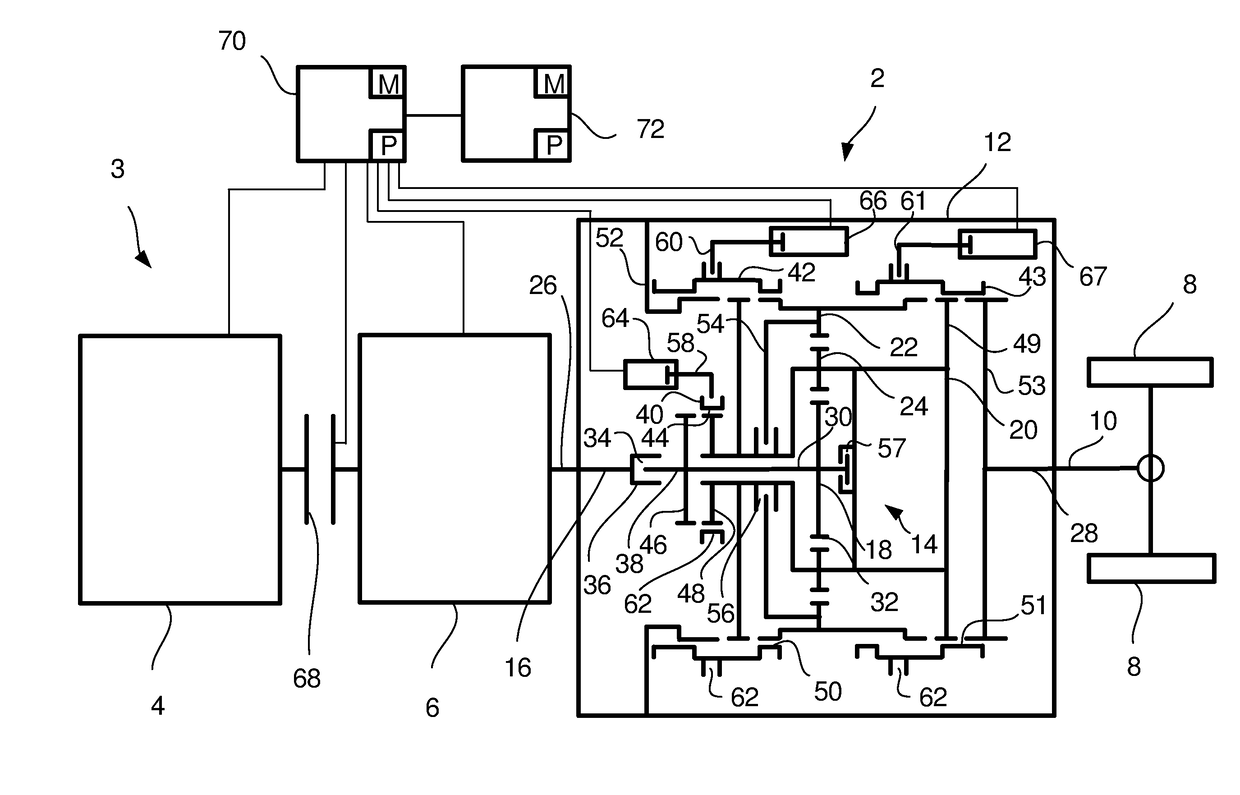
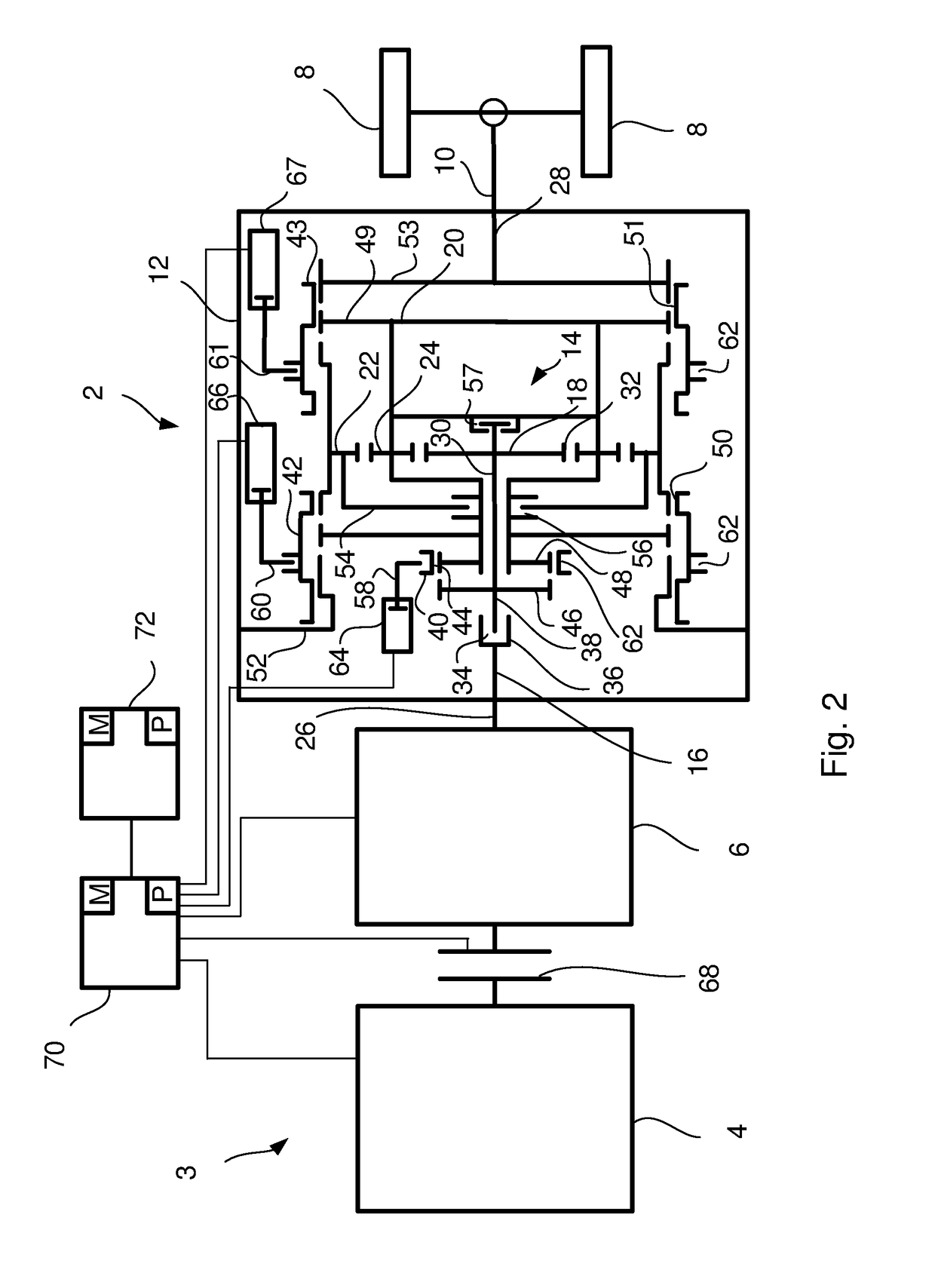
[0049]FIG. 2 shows a schematic sectional view of a gearbox 2 according to the present invention. The gearbox 2 usually comprises a planetary gear 14, which has a low and a high gear, with which the gearing possibilities of the main gearbox 6 may be divided into a low range position and a high range p...


PUM


Abstract

A gearbox comprising a planetary gearbox with a ring gear, a sun wheel and a planetary wheel carrier, on which at least one planetary wheel is rotatably mounted, which ring gear and sun wheel engage with the at least one planetary wheel; and a first axially shiftable coupling sleeve, which in a first gear position disconnects an input shaft from the planetary wheel carrier, and in a second gear position disconnects the input shaft with the planetary wheel carrier. A second axially shiftable coupling sleeve arranged to connect a gearbox house with the ring gear in the first gear position, and to disconnect the gearbox house from the ring gear in the second gear position. A third axially shiftable coupling sleeve arranged to connect the ring gear with an output shaft in a third gear position, wherein the second axially shiftable coupling sleeve arranged to connect the planetary wheel carrier with the gearbox house in the third gear position.

Description

CROSS-REFERENCE TO RELATED APPLICATION(S)[0001]This application is a national stage application (filed under 35 §U.S.C. 371) of PCT / SE2015 / 050526, filed May 12, 2015 of the same title, which, in turn claims priority to Swedish Application No. 1450626-5, filed May 27, 2014, of the same title; the contents of each of which are hereby incorporated by reference.FIELD OF THE INVENTION[0002]The present invention relates to a gearbox for vehicles and a vehicle comprising same.BACKGROUND OF THE INVENTION[0003]For vehicles, and in particular heavy goods vehicles such as trucks, a gearbox, also called a range gearbox, is often connected to the main gearbox with the objective of doubling the number of potential gearings. Such an additional gearbox usually comprises a planetary gear, which has a low and a high gear, with which the gear possibilities of the main gearbox may be divided into a low range position and a high range position. In the low range position, a gear reduction occurs through ...

Claims


Application Information

Patent Timeline
IPC IPC(8): F16H3/54F16H37/04
CPCF16H3/54F16H37/042F16H2200/2038F16H2200/2005F16H2200/0034F16H2003/447F16H37/046F16H2200/2094F16H2200/2043F16H2200/2064F16H2037/049F16H57/023F16H2057/02026F16H2057/0235
Inventor SLAPAK, DIETER
Owner SCANIA CV AB
Why Eureka
Eureka Blog
Learn More