Procedure for upshifting gear in a motor vehicle and a power plant unit for a motor vehicle

A technology for shifting high gears in motor vehicles, which is applied in the field of high gear shifting in motor vehicles and power plant units of motor vehicles, which can solve the problems of reduced vehicle comfort, drive train stress, vehicle bumps, etc., and achieve the effect of eliminating reaction time

Inactive Publication Date: 2008-04-02
VOLVO LASTVAGNAR AB
View PDF10 Cites 0 Cited by
  • Summary
  • Abstract
  • Description
  • Claims
  • Application Information

AI Technical Summary

Problems solved by technology

If this synchronization does not happen relatively slowly, too much positive torque is obtained in the driveline, and if it is synchronized too quickly, the opposite can cause the vehicle to jerk and the driveline to be subjected to unnecessary stress
Also, the comfort of the vehicle will be reduced due to the bumps

Method used


Image

  • Procedure for upshifting gear in a motor vehicle and a power plant unit for a motor vehicle
  • Procedure for upshifting gear in a motor vehicle and a power plant unit for a motor vehicle
  • Procedure for upshifting gear in a motor vehicle and a power plant unit for a motor vehicle

Examples


Embodiment Construction

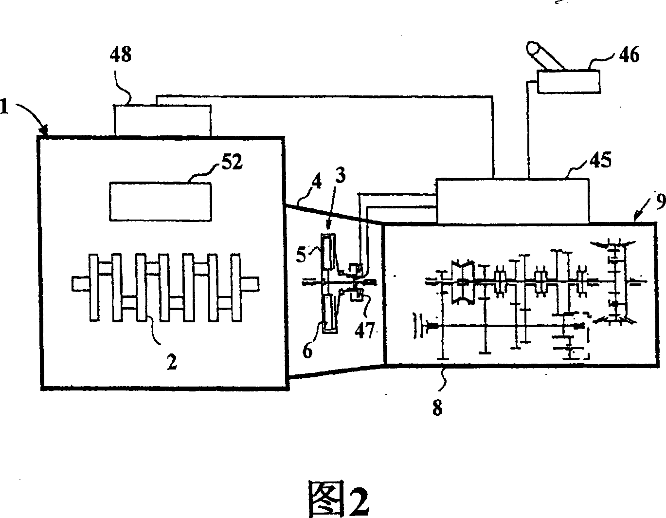
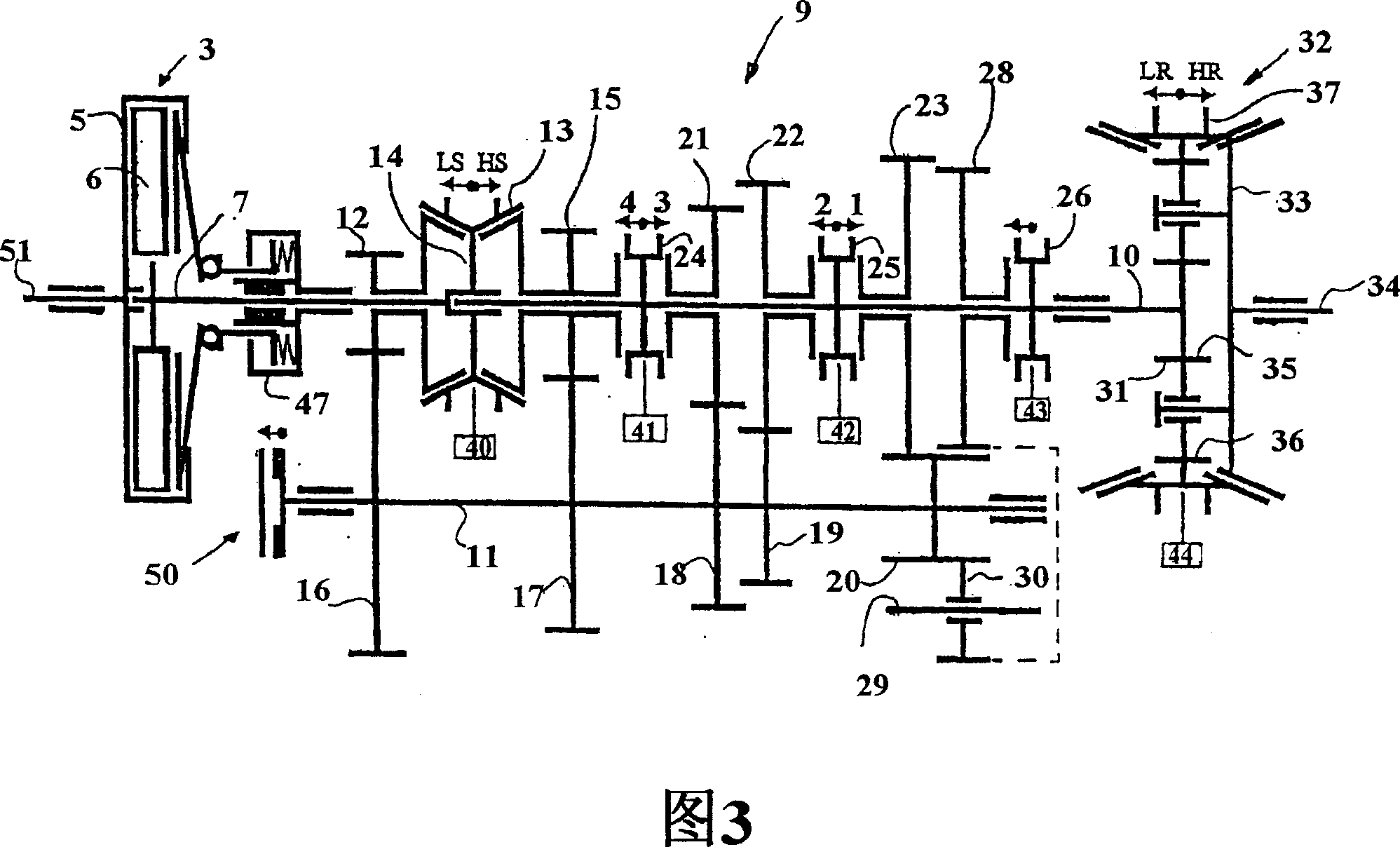
[0028] In FIG. 2, reference numeral 1 designates a six-cylinder internal combustion engine, such as a diesel engine, whose crankshaft 2 is connected to a single-plate dry disc clutch, designated by reference numeral 3, which is housed in a clutch housing 4 . The double disc type can be used instead of the single disc clutch. Through the output shaft 51 of the engine (see Figure 3), the crankshaft 2 is non-rotatably connected to the clutch housing 5 of the clutch 3, while its disc 6 is non-rotatably connected to the input shaft 7, which is rotatably is installed in the housing 8 of the gearbox, generally indicated by reference number 9 . Main shaft 10 and intermediate shaft 11 are also rotatably mounted within housing 8 . It should also be noted that the engine control unit 48 , the transmission control unit 45 and the manual gear selector 46 connected to the transmission control unit 45 . The transmission control unit 45 and the engine control unit 48 are adapted to communi...


PUM


Abstract

Procedure for upshifting gear in a motor vehicle, comprising an internal combustion engine (1) with an engine-braking device (52), an automated disk-clutch (3), a multi-stage gearbox (9), in the casing (8) of which an input shaft (7), an intermediate shaft (11) and a main shaft (10) are mounted, and braking means (50) for braking the intermediate shaft (11), and where, when the upshifting takes place, the disk clutch (3) is disengaged and the intermediate shaft (11) is disengaged from the main shaft (10), the braking means (50) being activated so that the rotational speed of the intermediate shaft (11) is adapted to the next gear selected at the same time as the rotational speed of the engine (1) is adapted to the rotational speed of the input shaft (7) in the new gear by virtue of the engine-braking device (52) being activated.

Description

technical field [0001] According to the preamble of claim 1 of the following patent, the invention relates to a method for upshifting gear transmissions in a motor vehicle comprising an internal combustion engine with engine braking, automatic disc clutch, belt Multi-stage gearbox with braking device, which is installed in the gearbox to brake the intermediate shaft. According to the preamble of claim 4 of the patent, the invention also relates to a device for said method. Background technique [0002] In this application, the power plant includes the vehicle's internal combustion engine, disc clutch, and gearbox; the drive train includes the engine, gearbox, and drive wheels. [0003] With the development of microcomputers, and the use of control computers and multiple actuators, such as servo motors, to precisely adjust the engine speed, the engagement and disengagement of automatic disc clutches between the engine and transmission, and the transmission relative to other ...

Claims


Application Information

Patent Timeline
Patent Type & Authority Patents(China)
IPC IPC(8): F16H61/02B60W10/02B60W10/06B60W10/10B60W30/18F16H3/12F16H61/04F16H61/21F16H61/70
CPCF16H2061/216B60W10/06F16H61/70F16H61/21B60W10/111B60K2741/025F16H61/0403F16H2306/48B60W10/02F16H3/12B60W30/18F16H2061/0411F16H2306/54B60K2741/286B60W10/04B60W10/10B60W30/1819
Inventor 埃里克·劳里斯万特·卡尔松马库斯·斯滕
Owner VOLVO LASTVAGNAR AB
Why Eureka
Try Eureka